
How to deal with power sources with low short circuit power? How to comply with the “Golden Rules” of electrical power distribution design in hybrid electrical power systems? These questions will become important for zero GHG emissions ships powered by fuel cells or other alternative electrical power sources. Solving related issues may not have standard solutions.
In recent years, we have seen a trend in designing propulsion systems aimed at reducing unwanted emissions to comply with existing and future regulations for seagoing vessels (IMO) or inland waterway ships (ES-trin regulations). At the same time, these new systems were intended to improve the fuel efficiency of propulsion and auxiliary systems in view of high fuel prices.
New fuels have been introduced, for example methane (CNG, LNG or dual-fuel) and more recently gas oil mixed with hydrogen. In future, other fuels are expected to be introduced, such as hydrogen as a sole fuel or fuels like methanol or ammonia. These fuels will be used in diesel engines or will power the ships with the use of fuel cells.
Additionally, the designs have changed based on the use of the vessel. Analysis of load balance and power consumption per voyage revealed that by optimising diesel engine operation to higher load levels, the specific fuel consumption (SFC) on a number of different ship types could be brought down.
Using electrical propulsion systems allowed designers to reduce consumption further by splitting one engine into two or three smaller engines, making it possible to use one or two small engines at lower propeller power load resulting in higher loaded engines and correspondingly lower fuel consumption. Moreover, an engine that does not run, uses no fuel and reduces the maintenance cost due to fewer running hours per year as an extra advantage.
Another solution was based on using diesel engines at variable speed, as R&D revealed that for a certain engine load, by changing the rpm, an optimal rpm point could be found resulting in a lower fuel consumption than at the engine rated speed. When using diesel engine generators, this causes a fluctuating frequency that is not suitable for consumers, as they may overheat or stop or break down if it deviates from the rated frequency by too much.
Semiconductor converters made hybrid systems possible
The mitigation solution for this problem was the use of semiconductor converters. The use of converters, however, leads to more cost and space use, so designers tried to optimise the vessel design to find the optimum solution for several constraints. Many ideas to achieve this have been published in literature. In principle the hybrid design was born.
Adding batteries
The next step was the analysis of the power use per minute or per second, because when the load on the diesel engine suddenly increases, it should not follow instantly as it would consume too much fuel. The solution was found in adding batteries, which provided for these load jumps, allowing the diesel to slowly adapt to the new load situation resulting in a lower fuel consumption.
This design is called peak shaving hybrid on the source energy side. Important is that the analysis of the power consumption and its fluctuations per voyage or time unit is known for the vessel and its intended use. That analysis should drive the possible application of the above mentioned specific solutions and designs.
These developments have resulted in hybrid solutions on the propulsion side and/or on the energy source side and many articles describing such systems have been published in professional papers. The semiconductor converters made these systems possible. These converters can be found on the supply side, such as between generators, fuel cell or battery and distribution system or on the user side between the supply system and propulsion or other systems.
This development was the driver for Lloyd’s Register to issue specific rules for hybrid electrical power systems, earlier in the year. These rules are focussed on energy distribution from source to user/propeller and depending on source and user type vice versa. Figure 1 gives some examples.
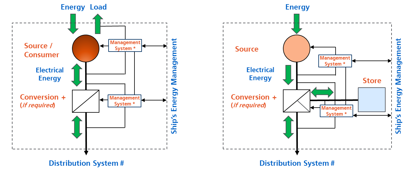 Figure 1. Energy distribution examples.
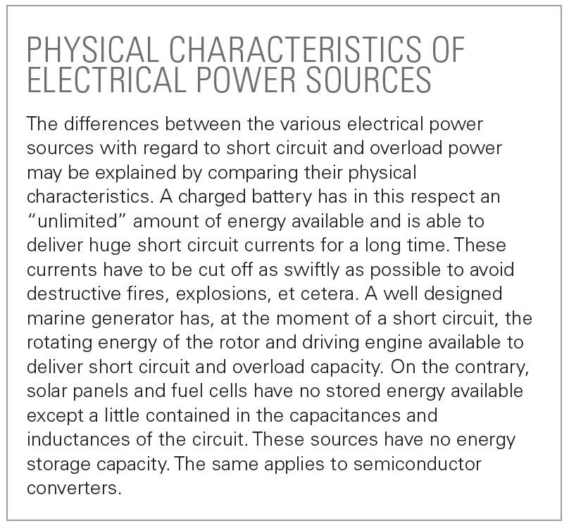
The source may be a generator, fuel cell, solar cell, flywheel, or battery, exhaust energy recovery system or a heat energy recovery system. However, each of these sources has its own specific characteristics, just like the semiconductor converters used in the systems built up with these sources. The figures 2 to 4 give the characteristics of different energy sources.
In practice, most converters are not capable of operating in the red and orange part of the graph in figure 4 due to built-in protection systems. A short circuit at the output of the converter will be immediately detected and the converter will switch off to protect itself and generate an alarm.
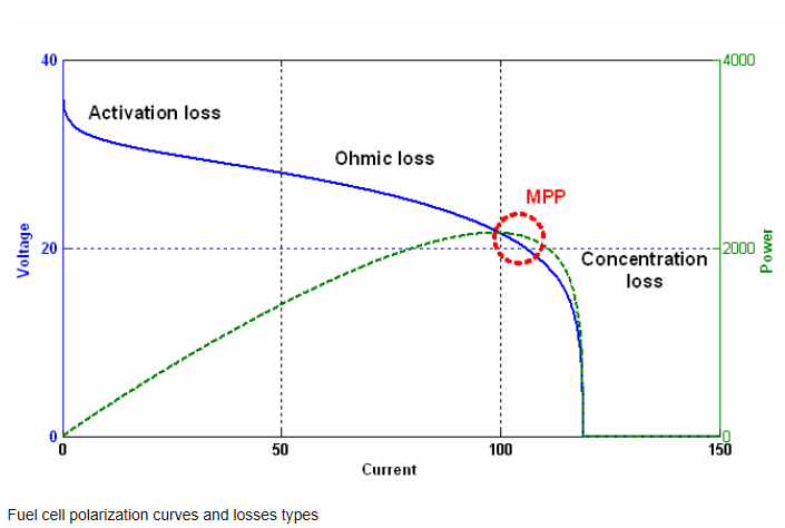 Figure 2. Characteristics of fuel cells.
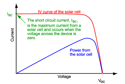 Figure 3. Characteristics of random solar cells.
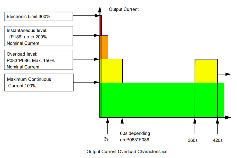 Figure 4. Characteristics of random converters.
The art of designing is to balance all these sources, converters and users (like propulsion or other auxiliary equipment), all with their own specific characteristics, in such a way that none of them will operate outside their Safe Operating Area (SOAR) when working together in an electrical grid system. And that this grid system, built up out of these ”Lego blocks”, satisfies the Golden Rules. And that may be quite a challenge!
Many designers have extensive experience with designs using standard components like diesel driven generators and electric motors. However, adding a storage battery or fuel cells to the system can render a standard design far more complex and the characteristics of these sources, so different from those of standard generators, must be duly taken into account.
Golden Rules
Classification societies and statutory regulations require compliance with the Golden Rules for electrical system design. The main Golden Rules are:
- Continuity of service.
- Under fault conditions electrics should not create fire.
- Not be dangerous/lethal to humans and animals.
- Discrimination during any fault conditions (to achieve item 1).
- Load control after black out recovery and load fluctuations (sequential start).
- Maintain/restore propulsion/steering gear.
- Control/alarm and safety systems to be separated.
The combination of the above rules 1 and 4 requires that upon a short circuit or an overload in the electrical installation, only the faulty circuit or component is being switched off. Normally, that requires that the short circuit or overload protection operates and disconnects the affected circuit through a fuse or circuit-breaker. Yet, this requires that the source supplying the system has adequate short circuit current capability.
For conventional marine generators, this is not a problem because these machines are required to deliver a minimum of three times the rated current at zero output voltage for two seconds (short circuit conditions) and 1.5 times the rated current for thirty seconds at full voltage (overload conditions).
If a new component, like a converter or a fuel cell, is used in a system, the designers need to check if that component with its specific capability graph does not jeopardise the Golden Rules. The following practical example arose in the past with the use of variable speed diesel/generator sets, introduced as explained above, to make the installation more fuel efficient. However, the equipment supplied by this system could not operate properly with the associated frequency range and a non-compliance arose with regard to rule 6.
The mitigation solution was found by adding a converter that adapted the variable frequency to a stable frequency with the same nominal power output over the whole variable speed range of the diesel engine. But this created a problem with rule number 4, as the converter could not be overloaded, nor had the capability to provide short circuit current to the downstream circuit breakers for tripping them on a downstream short circuit fault.
This problem is completely different from the electrical protection problems of a few years ago when large storage batteries were introduced on ships
Subsequently, the designers solved the problem by increasing the capacity of the converter, providing what is called “ride through capability”. In order to do this successfully, the rated current of the converter had to be increased to three times the rated current of the largest outgoing circuit and requires additional special software for “ride through”. Such a special adaption of the SOAR capability results in more cost and larger converters, but is nowadays obtainable from several manufacturers such as Danfoss/Vacon, ABB, Ingeteam and Siemens.
It is perhaps interesting to note that this problem is completely different from the electrical protection problems of a few years ago when large storage batteries were introduced on ships and designers had trouble to find equipment and systems to deal with the huge short circuit currents that could be delivered by these batteries. Lloyd’s Register then developed the ultra-rapid switching theory for the DC systems and the associated research to provide systems with proper discrimination. These systems are now used in large yachts and other vessels under full class certification (see SWZ|Maritime, June 2014, “Designing DC grid systems in compliance with SOLAS and class” written by Ing G. Vromans).
Impact of using zero GHG emission technology
So how will this be when we prepare our ships for zero GHG technology with energy sources like solar cells, fuel cells, semiconductor converters, and so on? What if the converter cannot be bigger (no space) and fuel cell cannot deliver any overload power or current? What if the power sources and converters cannot deliver sufficient short circuit current or overload power? That means full non-compliance with Golden Rules 1 and 4 as well as with class and statutory requirements. A fundamental issue! How to solve it?
- Add bigger converters with ride through capability and special software.
- Or a tougher solution: use a DC grid design which requires special knowledge to comply with rules 1 and 4. Only a few companies can engineer this at the moment, as it requires design simulation in time domain.
- Use two fully independent grids with fully redundant users (single user supplied from both sides is very complex to solve, but not impossible, as any fault should not impact/influence both grids).
- Fundamental out of the box engineering solution.
- Add generators that can produce sufficient current to achieve Rules 1 and 4 by means of standby generators automatically connecting (for inland waterway ships presently not allowed by statutory ES-trin regulations).
For solutions 1 to 3, see the article in the June 2014 edition of this magazine, referred to above.
Outside the box fundamental engineering solution?
At present, all system designs achieve compliance with Rules 1 and 4 by current discrimination. What if we apply voltage discrimination? Voltage discrimination is hardly used in power grids, but is often used in outputs of laptops, electronics, and uninterruptable power supplies. It is also called a short circuit proof component. It literally means you can short circuit the output and nothing happens, and nothing burns or breaks down. And when the short circuit fault is removed, it looks like a kind of auto repair and the output will work as normal. Some USB connections work like this.
So if we could combine this “voltage discrimination” with “fault locating technology”, we could actually isolate the particular short circuit point automatically and Rules 1 and 4 would be complied with. Problem solved.
Voltage discrimination with fault locating technology could solve the problem
Such a system has been described in the new Lloyd’s Register Rules on hybrid power systems. Fault locating technology is not often used in grid designs due to the extra cost, but examples are zone fault detection systems (used in dynamic positioning systems) and, as simple example, earth fault detection by means of current transformers for major power users or distribution sections.
So far as known, it has not yet been used in marine electrical power grids, but how would such a combination of voltage discrimination together with fault locating technology look like while fitting class requirements? The following analysis is based on a hypothetical grid design like hereafter with circuit breakers to explain the problem setting and possible solutions.
Figure 5 is a standard possible setup of a grid given and suppose that to achieve the zero emission driver both generator/diesel sources are replaced by two batteries or two sets of solar cells or two fuel cells with alternative fuel like H2 or any combination of it all. Then we get in principle an electrical grid for a zero emission ship.
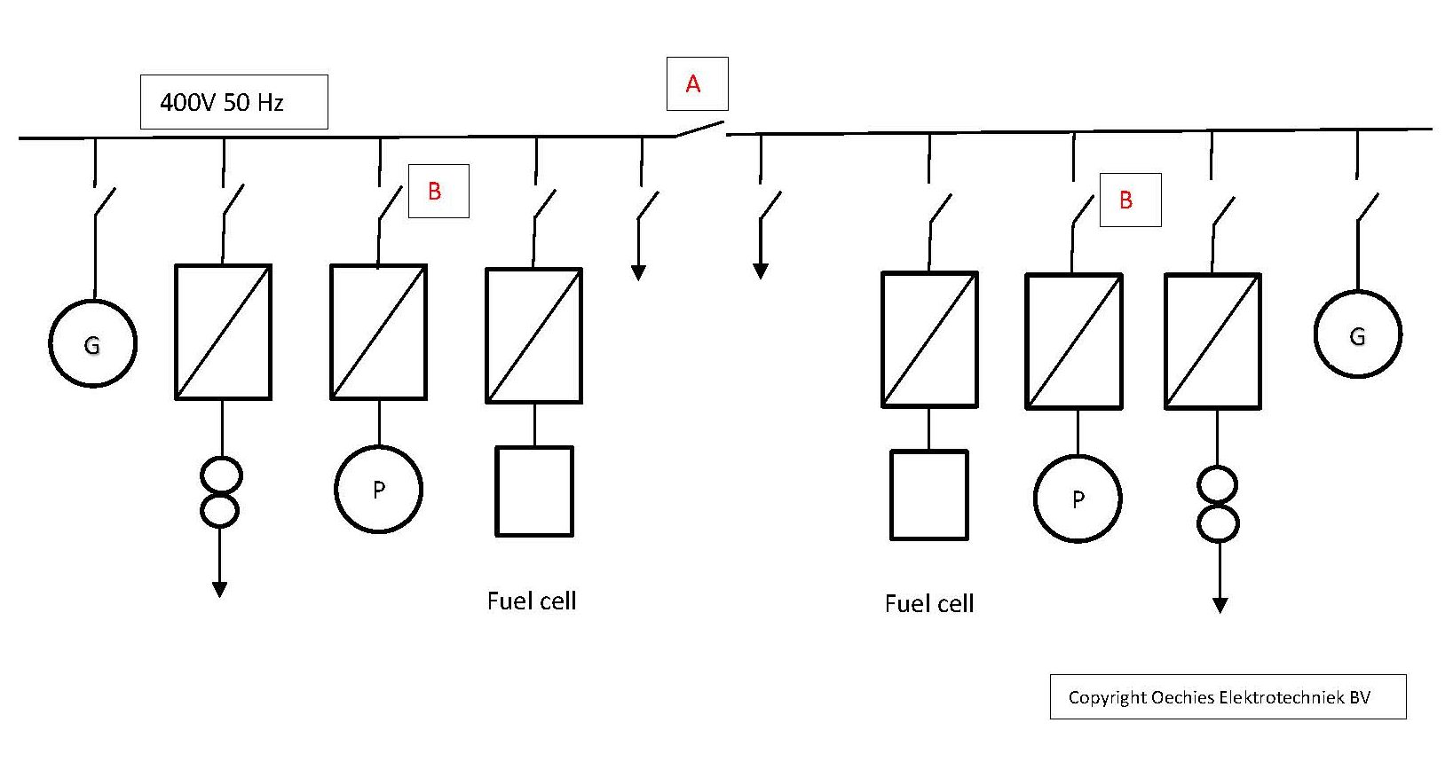
Figure 5. Hypothetical grid design with circuit breakers.
Problem definition
What if the source is a fuel cell or battery via converter and cannot supply the source energy required to trip circuit breakers B and/or A (if A has protection built in) under fault conditions? We have a full non-compliance against Rule 1.
It has to be noted that energy sources like fuel cells, solar panels and converters are only able to supply short circuit currents during around 100 microseconds or less whilst the circuit breakers need between three to 100 milliseconds (typically fifty milliseconds). This means that when the circuit breakers are supposed to be operated by its protection devices, the source energy is gone/depleted.
Consequently, the circuit breaker will not operate, the fault will not be isolated ending in total grid zero voltage. We have what is called a multiple frequency domain operation problem. So Golden Rules 1 and 4 cannot be met and the fault problem would lead to permanent black out!
The outside the box solution
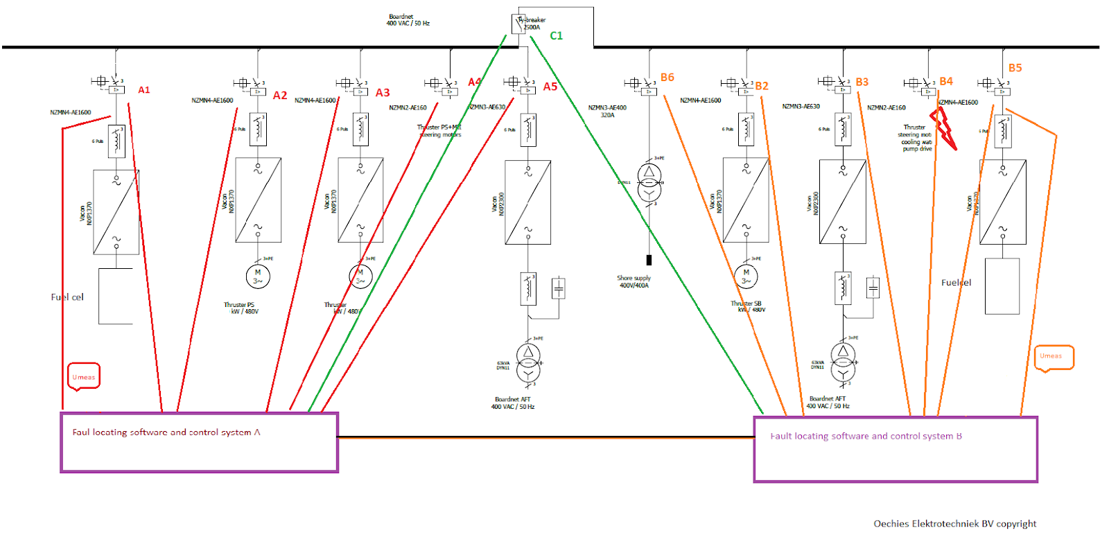
A voltage discrimination design with fault locating technology could solve the problem above and would look like figure 6. In this example, the battery/generator is replaced by a hydrogen fuel cell on each side of the tie-circuit breaker, which can only deliver low currents under short circuit conditions.
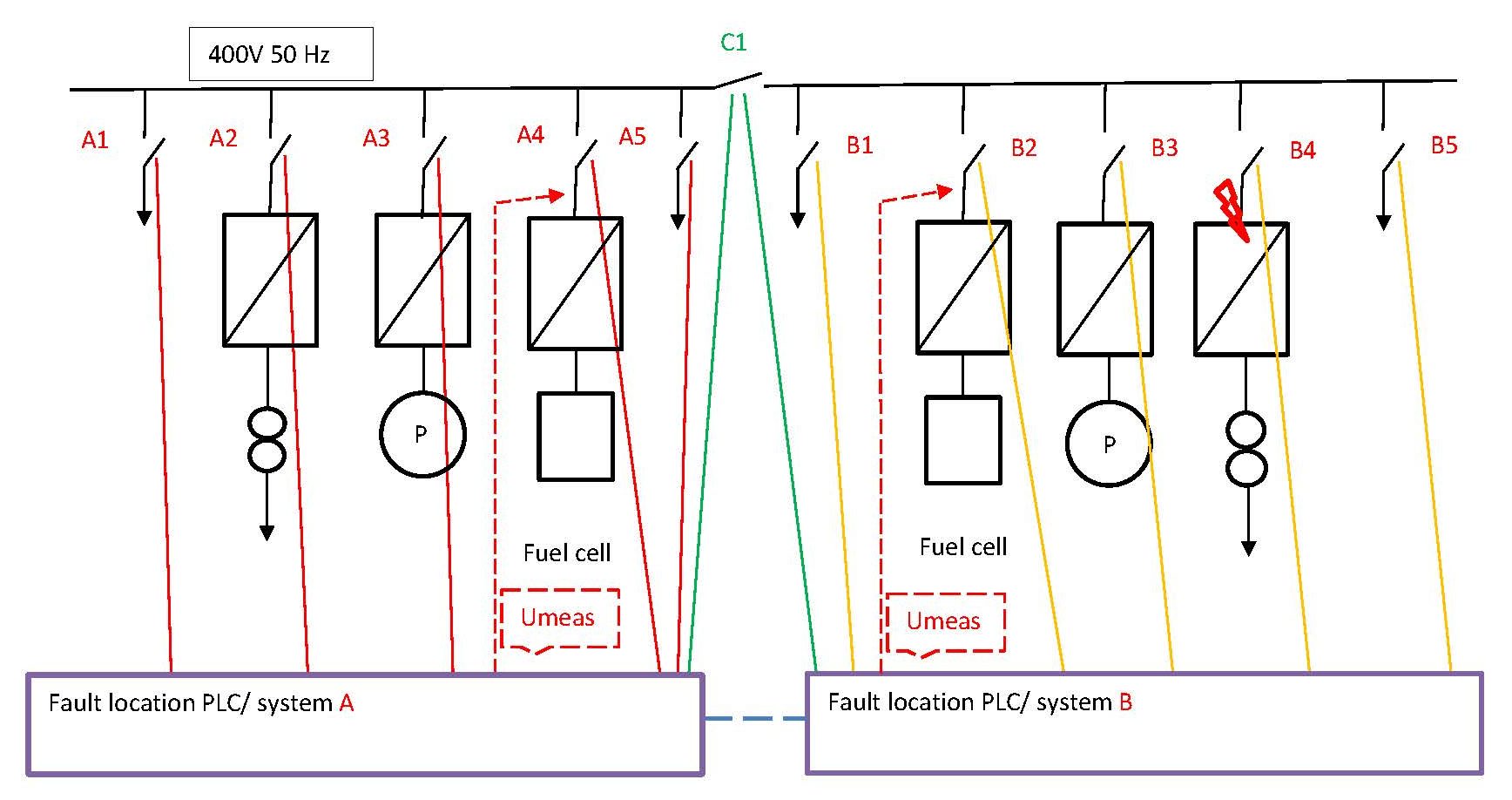
Figure 6. Voltage discrimination design with fault locating technology. This schematic drawing is printed with permission from Oechies Elektrotechniek BV.
Sequence of events
If the arrow on location B4 represents a downstream short circuit, the circuit breakers (Cb) will not trip due to reasons explained above. The fuel cell system sees the output voltage as zero with a maximum current, causing the fuel cell safety controller to stop after a limited time the hydrogen supply valve, and so a permanent black out situation would occur.
- The fault location technology system A will now detect zero voltage at the voltage measuring points (Umeas) and all associated circuit breakers will trip including the tie breaker.
- If the Umeas does not recover, it means either a problem in the fuel cell unit or in its converter. Nothing to do with a short circuit.
- If the Umeas measures the voltage coming back to normal, the fuel safety logic will not close the hydrogen supply valve and keep producing voltage to the converter.
- The fault location technology system A will now close the circuit breaker A1 and B5 of the converter to the grid and if Umeas stays normal, it means there is no fault on the busbar. If the voltage stays low, it means a main busbar short circuit, an alarm is generated and converter Cb switches off until a manual reset is activated.
- Voltage is OK, so Cb A2 will be closed, and Umeas stays OK, fault location technology system will try to close to Cb A 3 till Cb A5.
- All stay closed as fault is on grid side B.
- Tie breaker C1 will only close via synchronisation unit (can be manual or automatic).
- And B grid side will happen in the same sequence by fault location technology system B.
- At first, B5 is closed and if voltage remains OK, the hydrogen fuel valve will not be closed and the fault location technology system will try to close B4, and now voltage will go to zero and the fault location technology system detects this and will open B4 and keep B4 open till manual reset is given.
- As Umeas will see voltage come back to normal, fault location technology system B will try to close B3 and in sequence B2.
- And so fault location technology system B has restored voltage and supply on grid B.
- Conclusion: the fault location technology system isolated the short circuit.
In this example, the circuit breakers’ own protection system had no purpose, so designers can replace the circuit breakers by cheaper magnetic contactors. If in the future solar panels become cheaper and smaller/fewer kW, the same solution could be used and also with other sources with similar short circuit characteristics.
 This was one of the articles of SWZ|Maritime’s electrical systems special published in May 2020. It was written by Gerard Vromans and SWZ|Maritime’s editor Willem de Jong.