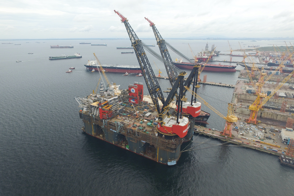
With its new crane vessel Sleipnir, Heerema Marine Contractors is gearing up for growth in demand for heavy lifting services. The ship’s lifting capacities far exceed those of Heerema’s Thialf, the previous record holder. In this respect, the Sleipnir’s design is a breakthrough.
The Sleipnir was built for transportation and installation of offshore structures, decommissioning of platforms, and projects in the renewables sector. By eliminating the need for scheduled dry-docking, its design could be optimised for the full potential of the cranes, resulting in unrivalled lifting capacity for this type of vessel.
At the same time, the vessel’s systems are developed in accordance with Heerema Marine Contractors’ (HMC’s) ambition to become a role model in the marine construction industry in terms of sustainability.
Design requirements
For concept selection, HMC’s design team compiled an operational profile, based on multi-year met-ocean conditions in the Atlantic Basin (North Sea, Gulf of Mexico, West Africa, Brazil) and other areas worldwide, including Australia and summer arctic waters.
A symmetrical twin-pontoon semi-submersible with four columns on both sides, proved superior operability. Considering the travelling distances between projects, the vessel had to be self-propelled, with a 10 knots cruising speed. DP3 requirements were to be met to enable safe operations in close vicinity to platforms and other structures.
A symmetrical twin-pontoon semi-submersible with four columns proved superior operability
The vessel’s strength and stability had to be commensurate to the tandem lifting capacity provided by the two cranes of 10,000 tonnes each. The ballast system had to allow slewing of a single 10,000-tonne load from main deck, with another 10,000 tonnes of remaining deckload.
Along with stringent safety and comfort requirements, HMC adopted impressive sustainable system requirements: marine gas oil (MGO)/liquid natural gas (LNG) power generation, selective catalytic reduction (SCR) to minimise NOX emissions, bio-friendly silicon based anti-fouling and waste heat recovery systems are a few conspicuous examples.
Main dimensions
The length of the deckbox was determined by the footprints of the cranes, the deckhouse and the size of a 10,000-tonne module along with other large objects carried on deck. The height of a module determines the crane boom clearance when stowed. Other dimensions of the deckbox follow the requirements of the vessel arrangement.
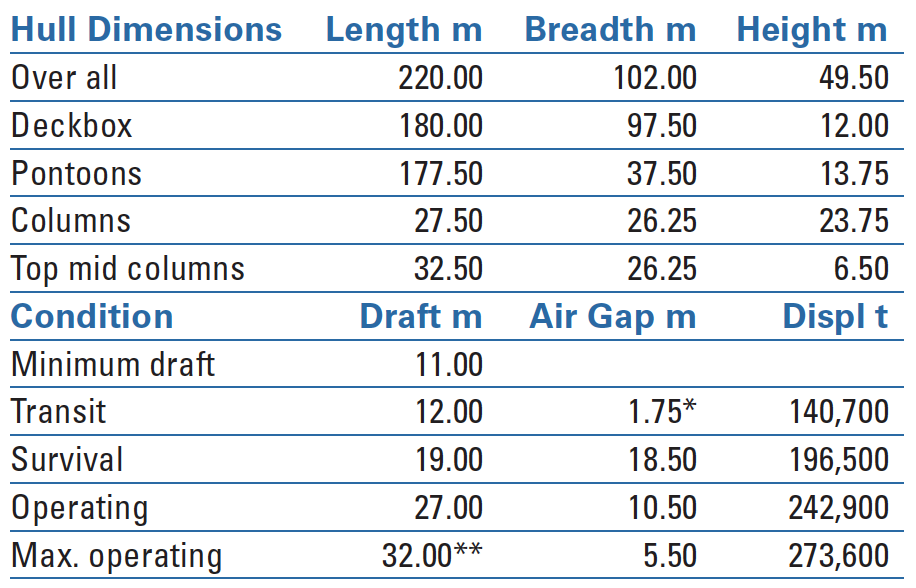
Main dimensions of the Sleipnir. Notes: * freeboard to top of floater; ** scantling draft displacement in seawater 1025 kg/m3.
The dimensions of large semi-submersibles are usually restricted by dry-dock dimensions, but not for the Sleipnir. HMC’s experience with underwater maintenance, endorsed by Lloyd’s Register, has proved regular docking unnecessary. The vessel’s main dimensions could, therefore, be optimised for motion behaviour and stability, resulting in maximum utility of the cranes.
The pontoon draft allows mooring at the shore base. A minimum freeboard prevents waves hitting the columns when sailing. The column height was determined by the wave crests in survival mode. A minimum airgap prevents waves reaching the bottom of the deckbox.
Hull shape
The hull has four columns on each side. The transparency of a multi-column structure allows passing of waves with lesser wave breaking and refraction. When submerged to operating draft, the hydrodynamic forces interacting on the hull parts result in minimum motion.
Semi-submersible crane vessel (SSCV) columns can be designed with larger waterline areas below the cranes, thereby obtaining a locally balanced weight and buoyancy. This, however, couples the pitch and heave motions in long swells, altogether affecting vessel operability. Therefore, the Sleipnir has comparable column waterline areas at operating draft. The upper regions of the mid columns widen, providing extra waterline area and stability required for extreme tandem lifts.
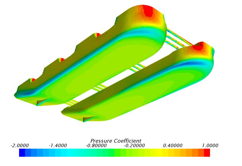 CFD analysis in current flow.
The shape of the pontoons fore and aft was adjusted to resistance and propulsion requirements. The sturdy, rounded bow resembles the shape of large bulkcarriers with proven resistance characteristics. That is why the vessel sails with the cranes forward. At the same time, it provides extra buoyancy below the cranes, but with much smaller pitch/heave coupling.
The pontoon sterns are elevated 17 degrees at full breadth, providing room for the large thrusters and a favourable resistance. The pontoons’ breadth extends inwardly, yet avoids interaction of wave resistance. The sterns are reinforced by skeg structures.

Hull cross section.
Crane vessel interaction
HMC preferred tub cranes over mast cranes. The tubs are integrated with the deckbox structure and fitted with large roller bearings, carrying the crane house with A-frame. The vessel’s stability, strength and ballast capacity are well balanced with the maximum lifting capacity of the two cranes of 10,000-tonne capacity each.
This by far exceeds the lifting capacity of the Thialf with its two cranes of 7100-tonne capacity each. The Thialf was Heerema’s largest semi-submersible crane vessel in operation before the Sleipnir and the previous world record holder in its class.
Regarding stability, HMC has applied strict self-developed vessel stability and motion requirements for keeping the crane boom within allowable side and off-lead angles. These are 3 degrees and 1 degree respectively in maximum load condition, including dynamics.
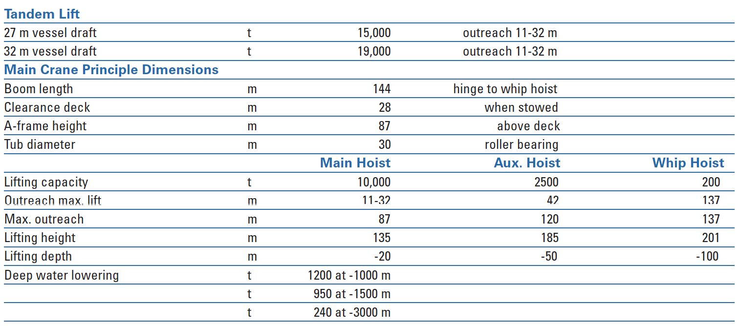 Crane dimensions. Notes: outreach measured to free edge; centre crane to free edge 16 m; lifting height and depth measured from sea level; t = tonne of 1000 kg, deep water lowering requires reeving out of main block, lifting heights from waterline at appropriate draft.
Structural arrangement
Wave loads are a major factor in the structural design of semi-submersibles. Waves passing from transverse and quartering directions can be critical in length and height. They create splitting forces between the columns, which are repetitive in a seaway. Therefore, each pair of columns is interconnected by three parallel braces to prevent the loads on the columns from acting on the deckbox. The braces are structurally redundant, one extra to a pair.
The columns are subdivided by bulkheads to create ballast and fuel tanks. A double shell (1.50 metres) protects the outer areas, complying with rules for mobile offshore units. It extends to the inner sides of the forward columns, where lifting barges will be moored. Vertical trunks for access, cabling and piping are arranged in way of inner bulkhead crossings.
The deckbox is a watertight box structure. As a hull girder, it is subjected to the loads of the cranes, which are substantial during maximum tandem lift. Overall strength is provided by the grid of longitudinal and transverse bulkheads. The bulkheads integrate the heavy main deck and the double bottom.
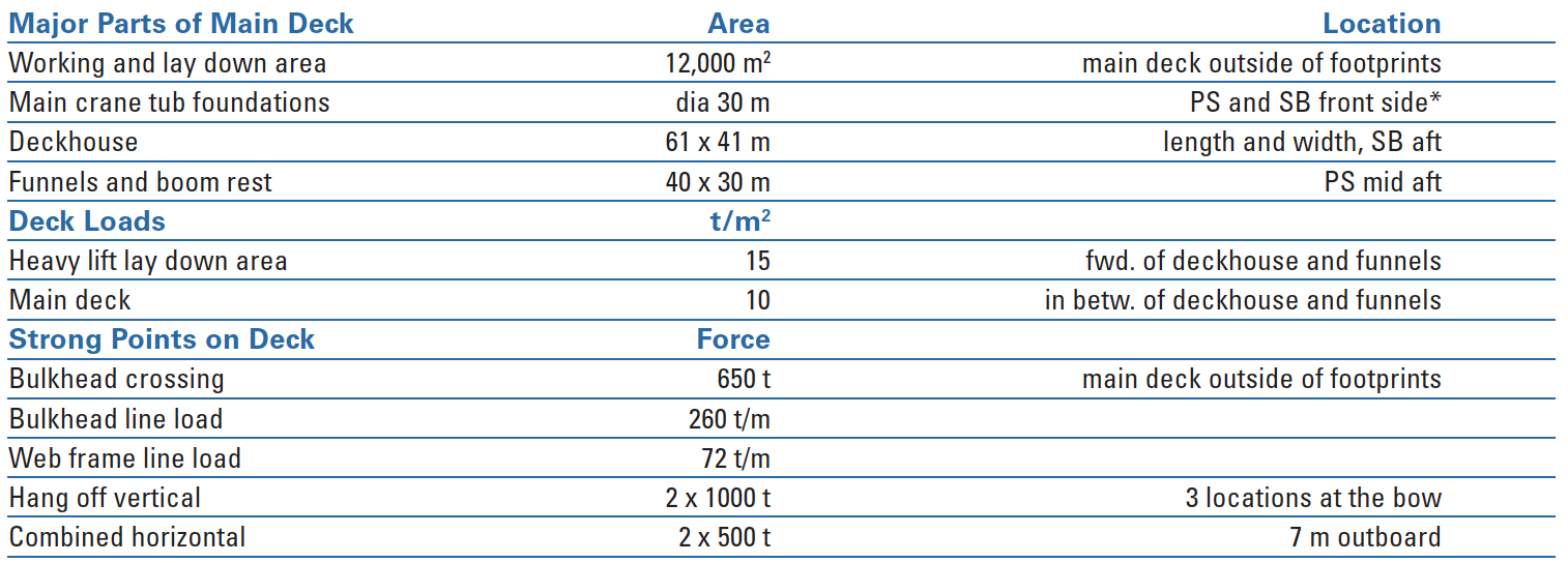 Main deck details. Note: *PS port, SB starboard.
The main deck plating is stiffened by transverse webs and longitudinal framing. This provides strong points in way of crossings and lines in way of bulkheads and webs. These will be used for sea-fastening of modules and other large structures. The plate panels are suitable to place heavy items. The double bottom provides local strength against wave run up in way of the column connections.
The longitudinal and transverse bulkheads of the deckbox follow the pattern of the column shells and bulkheads. Holds for storing LNG cylinders have been arranged in the mid columns and continue through the deckbox up to tweendeck. Technical rooms for gas processing and cofferdam spaces are next to the cylinder holds.
The areas on lower and tweendeck, portside (PS) off centre, are largely occupied by four separate engine rooms and four electrical switchboard rooms, complying with DP3 requirements for fire and flooding. The remaining deck areas are dedicated to living quarter utility rooms, warehouses and workshops.
The outer areas fore and aft are reserved for mooring equipment. In the deckbox’s sides, on lower and tweendecks, recesses are arranged as local weather decks for hose handling and other outboard related equipment. These recesses as well as the mooring equipment rooms are beyond the watertight boundaries of the deckbox.
Accommodation, helideck and life boats
A large six story deckhouse is located at the starboard (SB) aft corner on maindeck. The lower tier is dedicated to general services, change rooms and offices. The upper tiers are arranged for cabins. The mess rooms, galley and food stores are located below the deckhouse on the tweendeck.
As the view from the bridge is partly obstructed by the cranes, a conning station is fitted on the SB crane tub
Recreation, entertainment and various technical rooms are further down on the double bottom. The deckhouse is designed for a complement of 400 persons, accommodated in 175 double, 45 single and five executive single cabins. The central control room and wheelhouse are on top of the deckhouse. As the view from the bridge is partly obstructed by the cranes, a conning station is fitted on the SB crane tub to achieve a complete view of the sea.
A helicopter deck is mounted on the aft side of the deckhouse, along with check-in/out rooms. Its strength is designed for AW101 helicopters (dynamic load of 15.6 tonnes). Its diameter (28.5 metres) allows for Sikorsky helicopters in accordance with Norwegian regulations.
Two blocks of free fall life boats are located at starboard and aft side of the deckhouse. They contain three boats each, along with mustering facilities. Each life boat has a capacity of seventy persons. A third block is on PS of the vessel on the funnel deckhouse. The lifeboats have a total capacity of 630 seats, generously exceeding the 150 per cent capacity as required by regulations.
Power generation and distribution system
The rating of the high voltage system is shown in the table on the previous page. The architecture of the power generation and power distribution system is based on a quadrant approach. Twelve main engine-generator combinations are arranged in four engine rooms. The three generators of each engine room are connected to a high voltage (HV) switchboard dedicated to this room. Each switchboard feeds power to two of the eight thrusters and to one of the two slip rings per crane (fifty per cent of crane power).
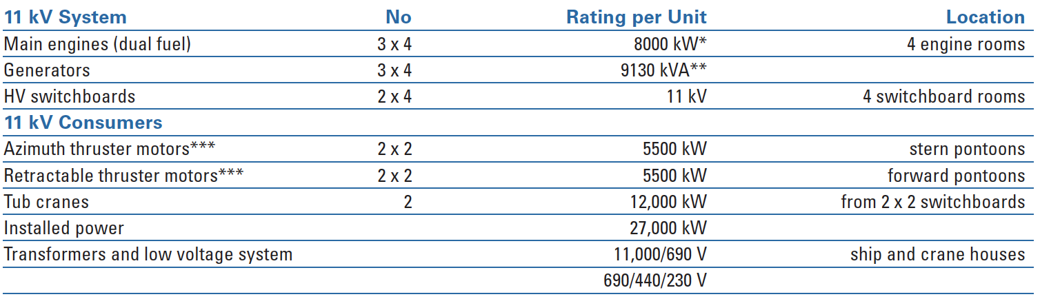 The Sleipnir’s high voltage system. Notes: kV kilovolt; kW kilowatt; kVA kilovolt-ampere; HV high voltage of 11 kV; * efficiency 97 per cent; ** cos phi 0.85; *** thruster rating of all mechanical and structural parts 6500 kW.
When sailing, the Sleipnir can operate with various combinations of engine rooms and power generators. The HV switchboards are typically interconnected in sailing mode, feeding the four stern thrusters. The vessel can maintain a cruising speed of 10 knots at a hundred per cent continuous rating of the four thruster motors. With all eight thrusters operating, a maximum speed of at least 12 knots is obtainable.
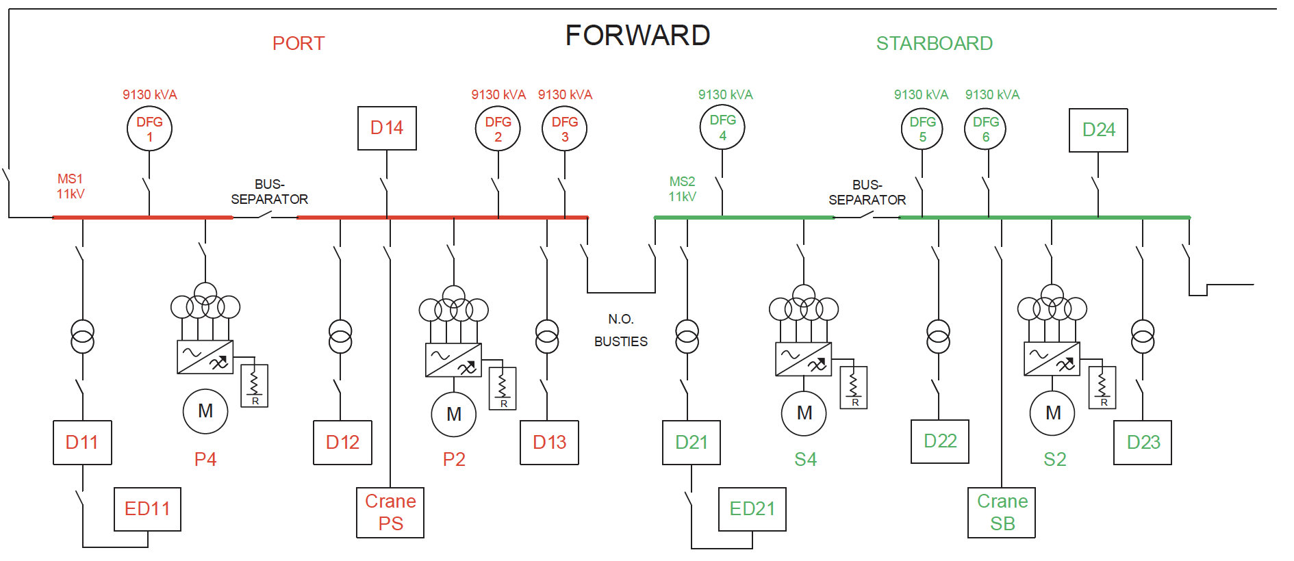 Electric one-line diagram forward; diagram aft is similar. Notes: DFG generator; MS main switchboard; M thruster motor; D, ED consumer groups.
In DP3 mode, eight thrusters are operating at 75 per cent rating. Upon the accidental loss of an entire switchboard or engine room, three remaining engine rooms with, associated HV switchboard, feed power to six remaining thrusters, operating at one hundred per cent rating.
Furthermore, in this accidental case, at worst, the power to one of the cranes is reduced to fifty per cent. This will slow down, but not interrupt an ongoing lift. The crane(s) will continue operating at half their rope speed maintaining maximum torque of the winches for completing an ongoing action in a safe manner.
The loss of one diesel generator will not affect the power required for the cranes or the thrusters at all in either dual, or single crane operation.
Fuel systems
The main engines are fuelled by either MGO or LNG. The dual-fuel concept complies with emission requirements of IMO 2018/20 and anticipates even more stringent coastal state requirements. MGO has a low sulphur content, but its emissions do produce NOX. Therefore, the installation includes SCR equipment and urea tanks for reducing NOX emissions in areas where LNG is not yet available.
LNG consists mainly of methane (94 per cent), produces very little NOX, no SOX or fine dust, and has a very efficient combustion process. The air-gas mixture will be sparked-off by high pressure MGO injection. The engines can instantly be switched over to MGO, ensuring availability should the LNG supply be disturbed. The LNG system arrangement as such is in compliance with DP3 requirements.
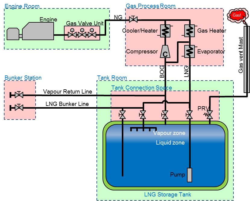 Principle diagram LNG fuel system.
All MGO and LNG bunker tanks are located in the mid columns, close to the vessel’s centre of gravity where the impact of partial filling on trim and heel is minimal. MGO tanks are located at the outer column sides and protected by a double shell, LNG tanks are on the inner sides. The vertical LNG cylinder tanks are built-in within the column structures, taking into account dynamic forces as well as buoyancy forces resulting from possible compartment flooding. The IMO type-C tanks are made of nine per cent Ni steel and are insulated.
A pipe connection space is located above each LNG tank. The deepwell pump line and the boil-off line are connected here. Boil-off gas is used as fuel gas, thereby maintaining the low fluid temperature. The space also contains the LNG bunker line and the vapour return line.
During filling, LNG vapour can be returned to the bunker vessel, if not used as fuel gas. A tank vent line leads to a central vent mast, next to the deckhouse. The deepwell pump line and the boil-off line lead to a gas process room. Liquid gas is vaporised and heated to fuel gas quality.
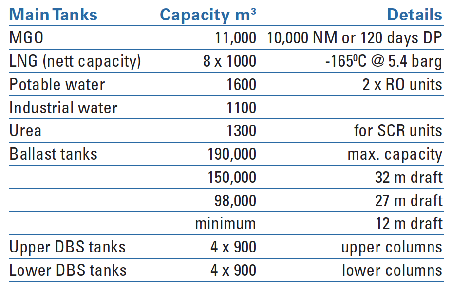 Tank capacities. Notes: MGO marine gas oil; NM nautical mile; DP dynamic positioning; LNG liquid natural gas; RO reverse osmosis; SCR selective catalytic reduction; DBS dynamic ballast system.
A single process room normally serves one engine room, but its capacity is rated for back-up services of two engine rooms. After processing, fuel gas is supplied to each engine’s gas valve unit for combustion.
The connection spaces as well as the gas process rooms are designed as hazardous areas, protected by gas and fire detection, a nitrogen inert system and an emergency shut down system. Interconnecting LNG and gas lines are all double walled and made of stainless steel. The LNG fuel gas supply system was delivered by TGE Marine. The dual fuel engines are MAN 8L51/60DFs.
Ballast system
The ballast system is separated per pontoon. Pumprooms (2 x 2) are located below the mid columns and their vertical access trunks. They are interconnected by pipe/access tunnels that also reach the thruster rooms. The ballast tanks virtually occupy the entire pontoon space and major parts of the columns.
Individual tanks are served by a ringmain from either of the pumprooms. Pontoon tanks are normally filled through seawater inlets and discharged by pumps. Column tanks are filled by pumps and discharged by gravity, vessel draft permitting. A pump capacity of 2 x 3250 m3 in each pumproom ensures arriving at operational draft within four hours. The survival draft can be reached within three hours in any condition, as required by class.
The ballast system is designed for control of draft and stability, as well as trim and heel during lifting operations at maximum load. Prior to lifting, the vessel will be ballasted with pre-trim and heel angles. Thereafter, the crane wires will be tensioned, followed by further ballasting for load transfer. Finally, the cranes take over for lift-off.
The ballast system is designed for control of draft and stability, as well as trim and heel during lifting operations
Lifting operations are thoroughly prepared by HMC’s engineering team. In practice, however, small deviations from the given centres of gravity may occur, particularly in the case of platform removals. Therefore, dynamic ballast tanks have been arranged in way of the fore and aft columns, both in upper and lower positions. The upper tanks can instantly be emptied during lifting for a last minute trim and heel correction. Similarly, the lower tanks can quickly be filled before touch down.
Such tanks have been developed for the Balder and Hermod with sufficient capacity to perform a complete lift off. Yet, this involved too much dynamics. The Thialf has no such system. HMC has now chosen for smaller tanks for lifting assistance only.
The majority of ballast water will be loaded and discharged on site, but part of it will be carried to other areas. Therefore, the four pumprooms are equipped with a ballast water management system (BWMS), in order to comply with IMO requirements.
The systems on the Sleipnir are based on the electro-catalysis principle. They are connected to the tank stripping systems and can handle 300 m3/hr. Treated water can either be circulated internally, or discharged overboard. The systems are delivered by Ocean Guard.
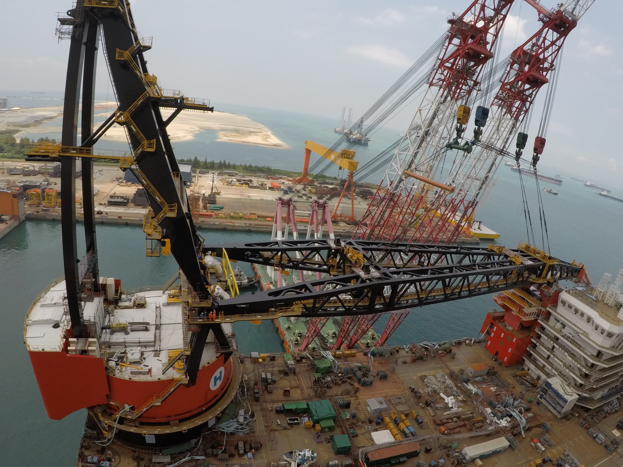 Crane installation at Sembcorp Marine, Singapore.
Thrusters and mooring system
The Sleipnir is equipped with eight azimuthing thrusters. Two aft and two forward in each pontoon. Their four bladed, fixed pitch propellers with nozzles are tilted down by eight degrees, to prevent their outflows from interacting with bottom plating and reaching the opposite pontoon. The units are designed for a bollard pull of more than 1030 kN, but can also be used for steering and propulsion.
The aft units are mounted above base line, the forward ones are retractable. This combi retractable/demountable feature is a new development of Wärtsilä and HMC, avoiding dry-docking and making all propeller/nozzle units interchangeable.
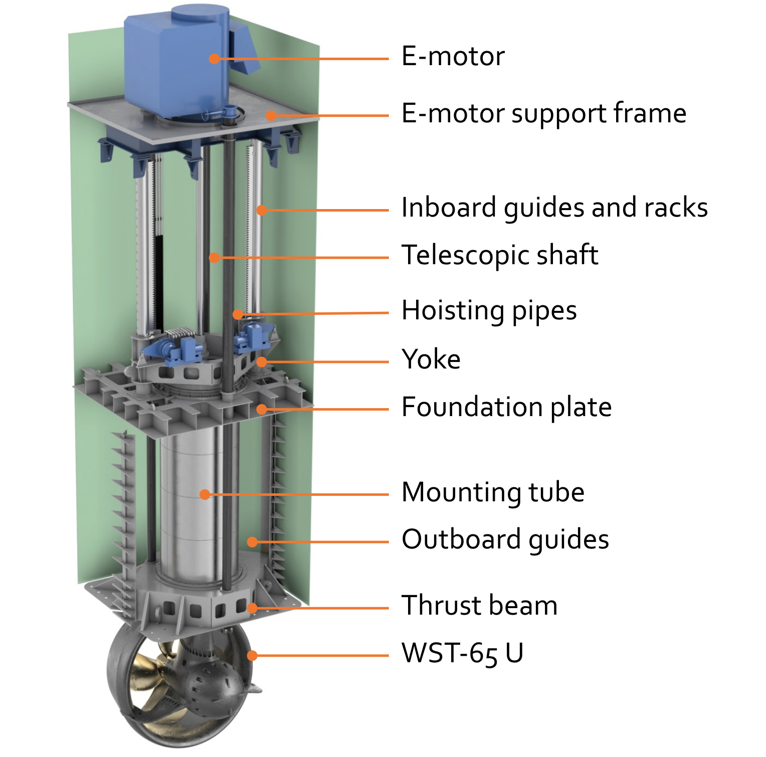 Retractable and underwater mountable thruster.
The vessel is also equipped with a position mooring system. Four bundles of three lines can be deployed from the corners of the vessel. The 3 ” lines are 1750 m long, two of the forward lines are 2450 m long. Fairleads have been fitted to the columns, but no anchor racks. When needed, 12 t high holding power anchors will be deployed from the main deck by crane. The 300 t winches are installed on tweendeck in fore and aft compartments.
Project development
The Sleipnir project started in 2012 with in-house studies on various vessel and semi-submersible concepts. HMC’s vision on required crane capacity developed from 2 x 8000 to 2 x 10,000 tonnes, along with the need of a very large deck area of 12,000 m2. This would enable installation of an entire field development in one go.
In 2013, the design package of the semi-submersible started at GVA in Sweden. The detailed design and construction phases followed in 2015 at Sembcorp Marine in Singapore. Two giant offshore tub cranes with an A-frame were ordered at Huisman, the Netherlands, in 2014. The cranes, built at Huisman China, were installed in Singapore in 2018.
In July 2019, the ship was delivered to Heerema. The Sleipnir arrived in Rotterdam for the first time on 22 March 2020, following a project execution in Trinidad. Before that it had already worked in Brazilian and Israeli waters. The vessel is due to depart at the end of March for the first of several decommissioning jobs across the North Sea.
This article was originally published in SWZ|Maritime’s October 2018 issue and written by Ir Rob Bos. He was specialised in the design of offshore vessels and FPSO installations and one of SWZ|Maritime editors. He passed away unexpectedly in August 2019.
SWZ|Maritime thanks HMC for its cooperation and for providing the information needed for this article: Sipke Schuurmans, Martijn Wijdeveld, Radboud van Dijk, Ewout de Gelder, Rieno Graveland and Michelle Brama.