
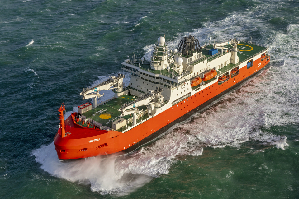
An icebreaker and a research vessel in one; according to Damen, the Antarctic Supply and Research Vessel Nuyina is the most complex ship ever built by the shipyard. SWZ|Maritime was invited to visit the ship on Thursday while it was still by the quay in Flushing, the Netherlands.
The project for a new polar research and icebreaking vessel started in 2013 with a request for proposal, issued by the Australian Antarctic Division. This design, build, operate and maintain contract was given to DMS, now Serco who in turn gave Damen Naval the contract for the design and build. The shipyard used a concept design developed by Knud E. Hansen from Denmark. The contract with Damen was signed in April 2016.
The ship is currently being readied for Arctic sea trials in July. Delivery to Serco is expected to take place shortly after these Arctic sea trials. After that, Serco will sail the ship with its own crew to Australia.
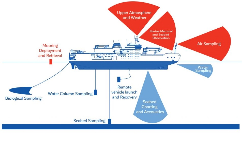
The 160-metre-long ASRV replaces the previous vessel 94.91-metre Aurora Australis and is designed for resupplying the stations and supporting scientific research in the Antarctic and Southern Ocean for the Australian Antarctic Division. Scientific research is focussed on global warming and protection of the (sub)-Antarctic eco systems. It also addresses the protection of wildlife and eco system based fisheries.
In November 2017, our offshore specialist/SWZ|Maritime editor Rob Bos (unfortunately now deceased) wrote an extensive description of the Nuyina even before it was built that highlights the ship’s special features. Extracts of this article are provided below, supplemented with pictures taken during our visit and the latest information we received on board.
9000 nautical miles and manoeuvring in ice
Whereas the Aurora could only visit one station before having to return to resupply and refuel in Hobart, the Nuyina can visit two, said project director at Damen Naval Joop Noordijk during our visit. However, to visit two stations in one roundtrip, the ASRV has to be able to travel 9000 nautical miles. In addition, thirty days of icebreaking in temperatures of -10°C and thirty days on station in temperatures of -30°C have to be taken into account. Essential systems and supplies should be available for six months to survive a besetment in the Antarctic.
Ice breaking operations must be carried out in sea ice of up to 1.65 m thickness at a speed of 3 knots. Where large sea ice sheets have collided, ridges may occur when crushed ice is piled up and frozen. It requires the vessel to ram on the ridge, followed by repeat actions astern and ahead. If a ridge is too strong, the vessel must manoeuvre itself free by astern and ahead movements whilst turning, so called star manoeuvring. This means helicopter reconnaissance flights are essential for finding a suitable passage elsewhere.
Seakeeping and icebreaking
Seakeeping and icebreaking hull shapes are basically different. A lot of effort has been spent in finding the best compromise to fit the mission requirement. As water depth is restricted near the stations, the vessel’s draft could
not be increased too much. Likewise, the beam should not be too wide to prevent stiff rolling behaviour.
The main size increase as compared to its predecessor Aurora was achieved by extra length, up to a point that manoeuvring in ice is still feasible.
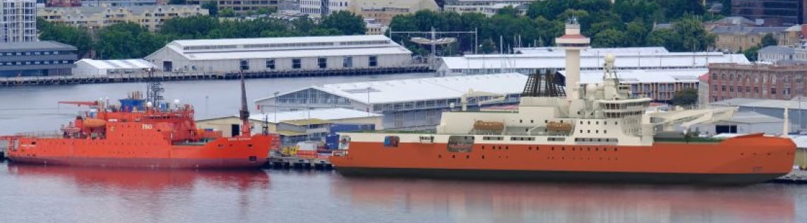
The Aurora (left) versus the Nuyina.
The main dimensions of the ASRV and the Aurora fit the collected icebreaker characteristics. The ASRV is the longest vessel in this collection, but an L/B ratio of 5.9 is a common value for cargo ships navigating in open water. These proportions will be favourable for both resistance and seakeeping.
Icebreaking hull form design
The bow of an icebreaker is designed for bending and breaking the ice layers ahead rather than crushing. The typical icebreaker bow has a small stem angle from the waterline down to the keel. The verticals in the bow area are designed with similar angles. In the horizontal plane, the waterlines are shaped with gentle curvature until joining the parallel hull. The cross sections in the bow area are also designed with gentle flare angles near the waterline. The ASRV hull design reflects these design guidelines very well.
When moving in ice, the sheet will be forced downward. The bending results in its failure and pieces of broken ice will submerge under the moving bow. The ship’s bottom is designed with a slightly raised floor. This helps the broken and submerged pieces of ice sliding aside rather than travelling the hull length. It avoids additional hull resistance and propeller-ice interaction.
The stern shape is dominated by the twin propeller and rudder arrangement. It shows a raked stern rising gently from the bottom line. The design waterline curves towards the centre for reverse icebreaking and manoeuvring in ice. Ice cutting knives are fitted at the stern and rudders for protection.
Long skegs are designed below bow and stern. These will limit the extent of riding onto the ice when ramming ice ridges and will prevent the vessel from getting stuck. The nose of the skeg limits the bow moving too far above the ice pack. Gondolas are fitted around the propulsion shafts and bearings for protection and support. They will prevent blockage of ice in both sailing directions.
The ASRV is classed by Lloyd’s Register as a 100A1 Research/Supply Ship, Icebreaker (+) and a series of notations for special features. Most obvious is the Ice Class PC3 notation, which qualifies the ASRV as a polar icebreaker suitable for year-round operation in second-year ice with multi-year ice inclusions. Winterisation rules are applicable to steel selection (-40°C) and systems design (-30°C).
Noordijk pointed out much of the piping on the open research deck for example is insulated and heated to prevent it from freezing over. ‘At the same time, the helicopter deck also has heat tracing to make sure it doesn’t freeze over.’
Hull arrangement
The ship’s watertight hull is defined by science deck-4, bottom and shell, fore and aft peak structures and seven watertight bulkheads in between. The double hull provides extra safety against hull impairment when operating in ice and shallow waters. This arrangement complies with the stringent damage stability regulations of special purpose ships and is favourable for temperature control of the inner compartments.
Horizontally, the hull is further subdivided by the tanktop-1, the machinery deck-2 and the winch deck-3.
The double bottom tanks are mainly reserved for seawater ballast and dirty water tanks. Smaller tanks in the centre are dedicated to engine room waste fluids and fuel overflow. The double hull spaces above the waterline are kept void as a freezing barrier, except for the fore and aft peak tanks. These are needed for trimming the ship one metre by the bow or stern during icebreaking to prevent the ship from becoming beset by ice.
In the mid-forward part of the hull, static heel tanks and dynamic roll suppression tanks have been arranged. Heel tanks are primarily for compensating crane operations, but also for assisting the anti-roll tanks by creating so called “duck walk movements” in ice. The anti-roll system will then be driven by air blowers.
In waves, the system will be used in passive mode. Anti-roll tanks are required because bilge keels and stabilisers cannot be applied. The U-shaped tanks are part of the double hull configuration with a pump room in the centre. Heating coils are fitted to prevent essential tanks from freezing.
Fuel tanks have been arranged in spaces within the protected inner hull. MDO tanks are mainly located around the engine room compartments and in the aft part. The cargo tanks can be found in the fore part of the hull and are designed for storing special arctic blend (SAB) fuel.
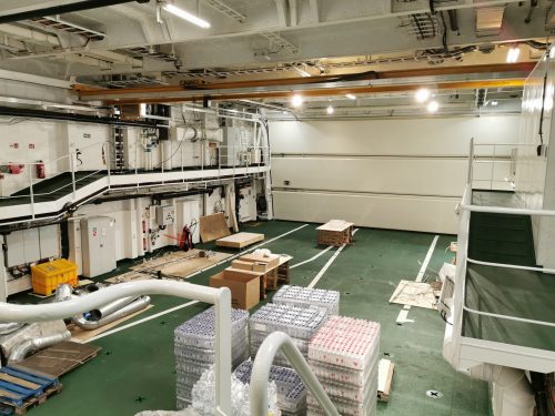
Two engine rooms are in the parallel midbody. Each one connects to a propulsion room and a switchboard room overhead on the machinery deck in a dual propulsion arrangement. In front of the engine rooms, two cargo holds have been arranged.
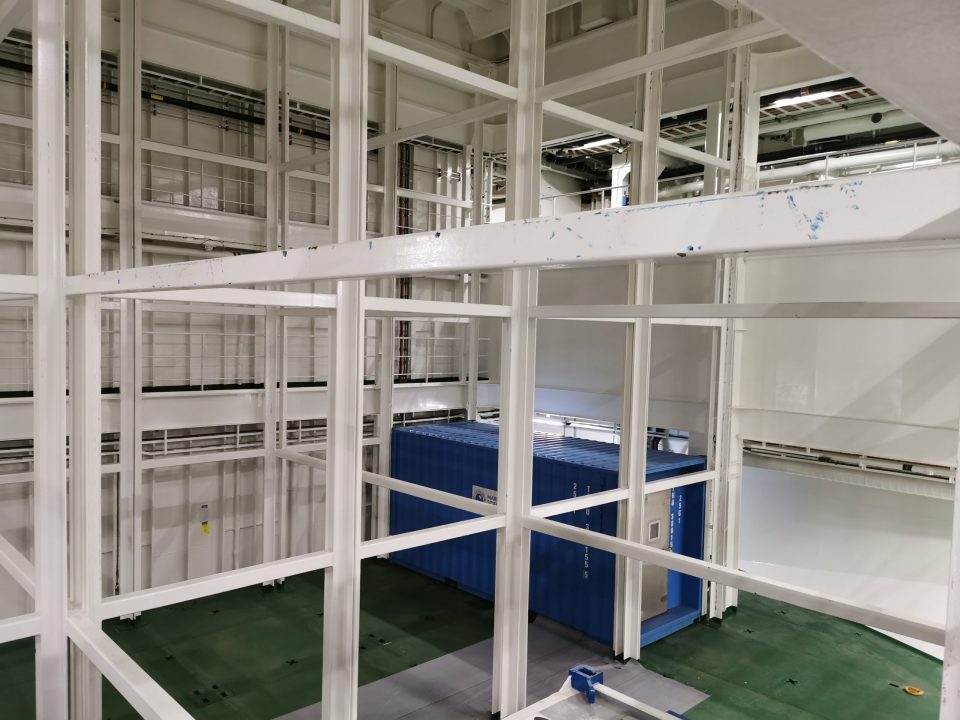
One of the cargo holds.
Hull steel and conservation
The shell plating below deck-4 is transversely framed. High tensile strength steel quality has been applied. Decks, bulkheads and the superstructures will be built in mild steel. Steel grades have been selected for -40°C. Above science deck-4, all plating is longitudinally framed.
The plate thicknesses applied in the parallel midbody are 16-17 mm, with an ice belt of 20 mm in way of the waterline. The shoulder area is 28-30 mm thick, the bow plating 32-35 mm. In the stern area, plate thicknesses range from 25-30 mm. Noordijk: ‘But there are also areas in the bow and stern where the steel is 60 to 70 mm thick.’
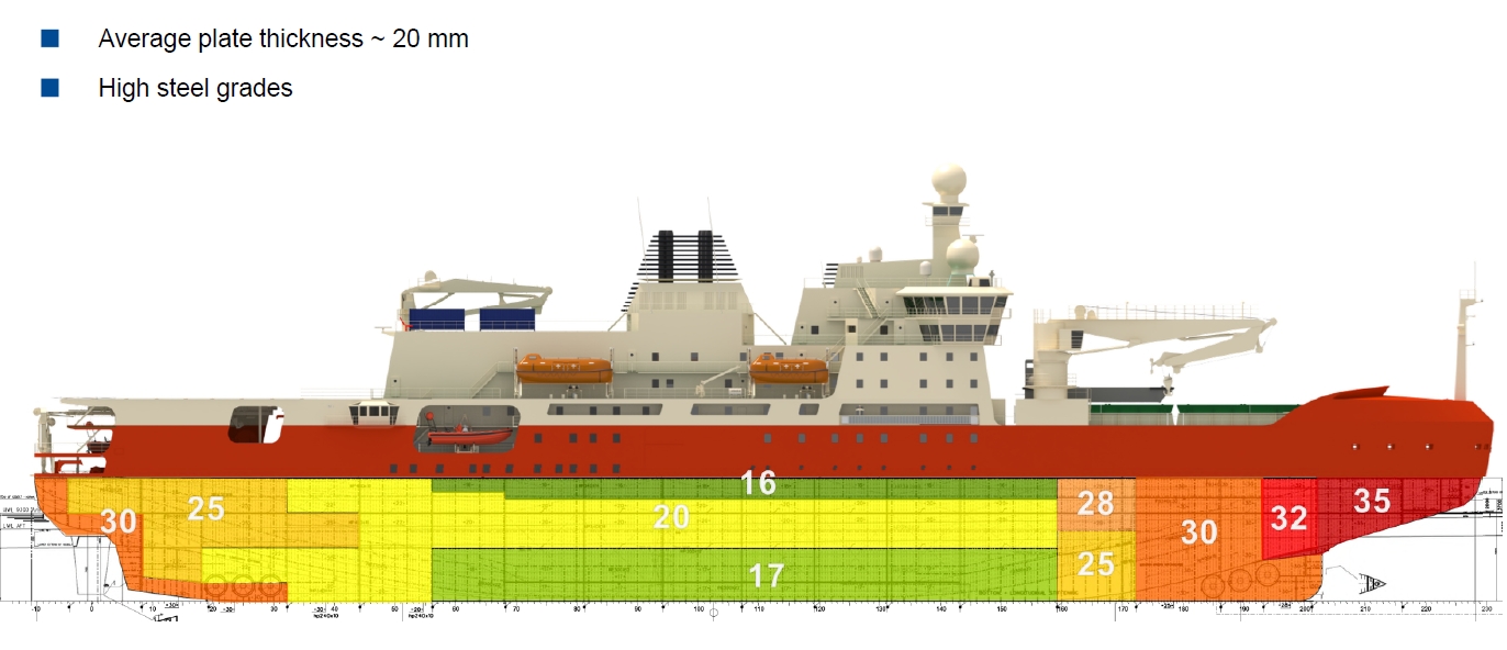
The internal hull steel structure is further reinforced by extra ice belt framing and large brackets. The outside welds will be grinded smooth, to avoid break down of the coating system and to minimise bubble generation and self-noise in way of the transducers. An abrasion resistant ice-coating will be applied for hull steel conservation.
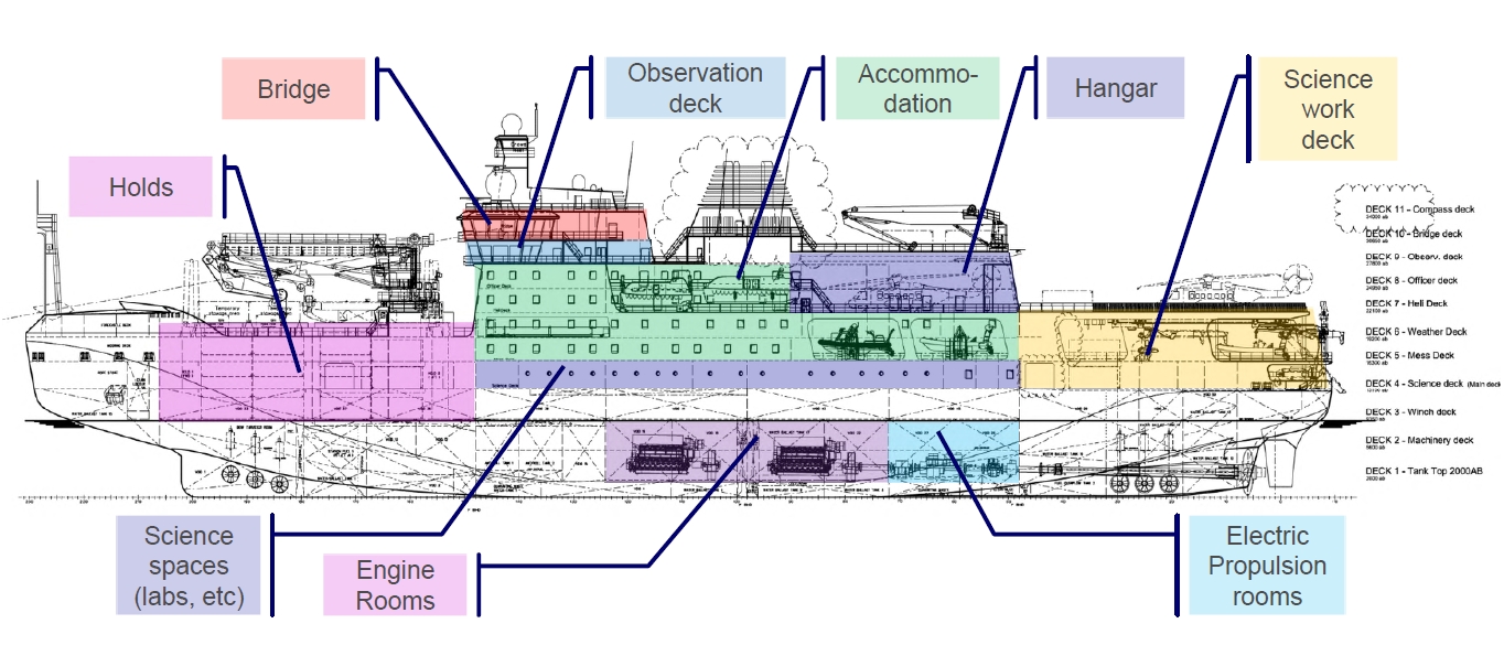
Superstructure and holds
A large superstructure is mounted on science deck-4. The structure is fully integrated with the hull side plating. It provides a science work space aft, three tiers of living quarters in the midbody and a weather deck upfront.
The work deck aft is designed for science operations. The area is open at the stern and protected by small deckhouses in the sides, as a continuous double shell. At starboard side, the work deck provides a passageway to the side deployment and moonpool area.
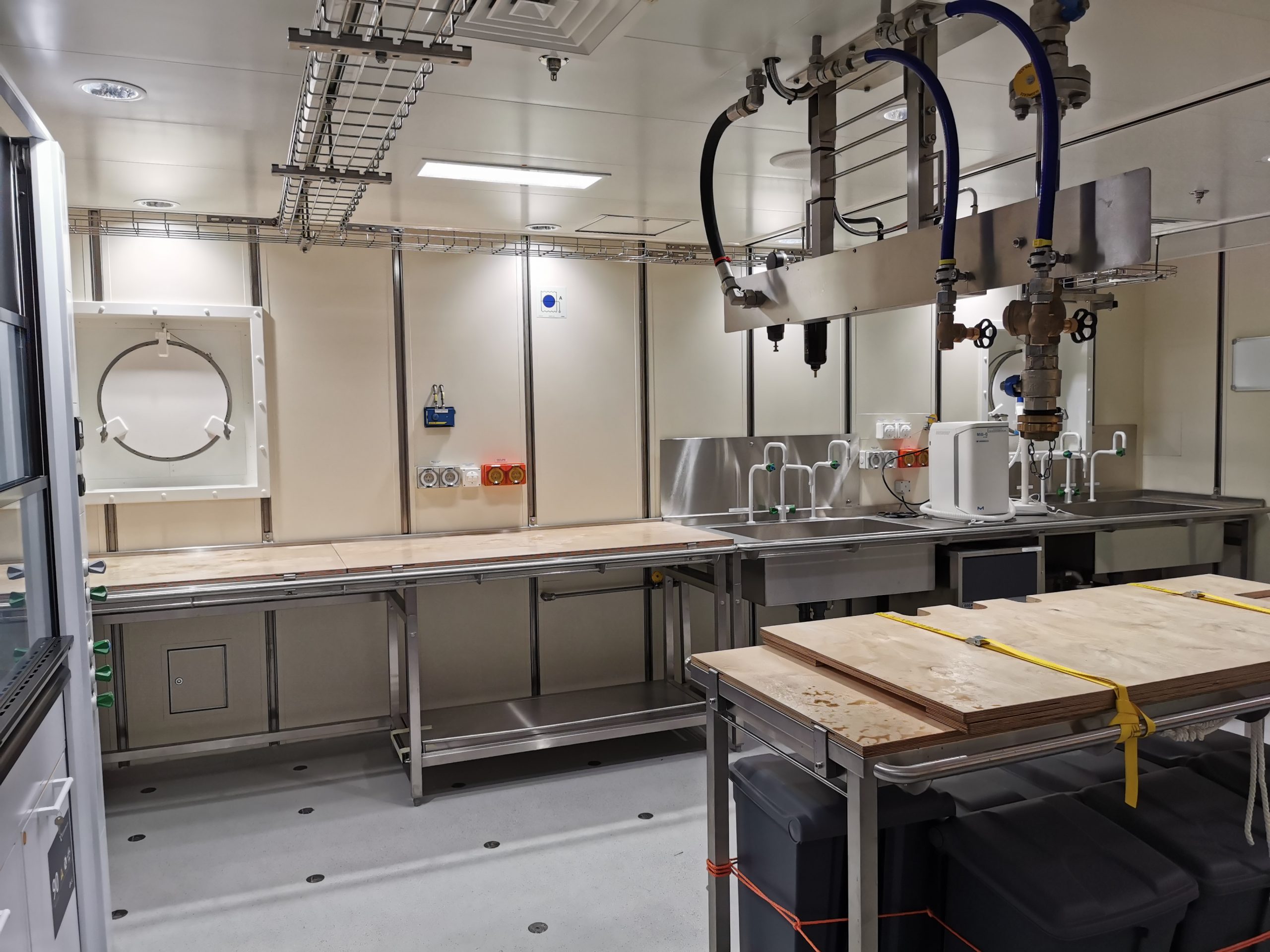
One of the laboratories on board the Nuyina.
The lowest tier of the living quarters is reserved for laboratories, utility rooms and a boat embarkation room. It has various science rooms and a control room for subsea operations. The accommodation space ends at the front bulkhead of a large theatre. The two tiers above provide accommodation for scientific personnel and crew in cabins for two.
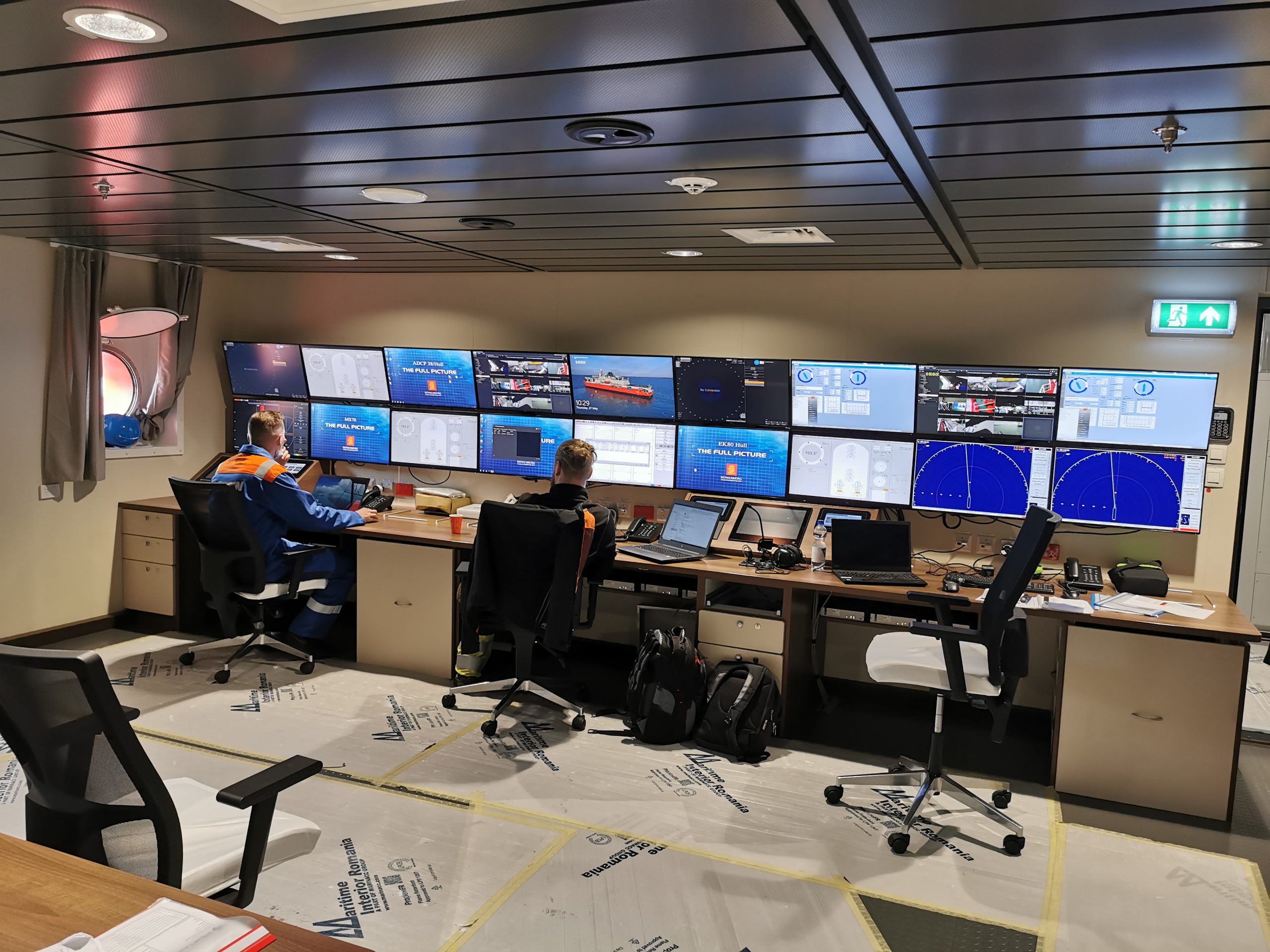
The science data centre.
Tweendeck-5 of the superstructure continues within the cargo holds. It has a large opening for containers being stacked up from the two decks below. Tweendeck-6 also continues in front of the accommodation as a weatherdeck and is fitted with coamings and hatches to close off the cargo holds.
Helicopter deck and deckhouse
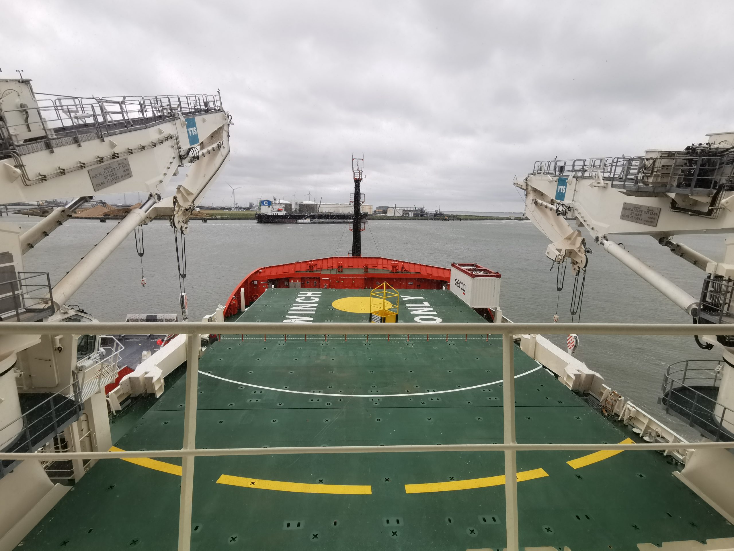
A flight deck has been arranged on deck-7 above the working area along with a helicopter hangar. The hangar is sized to stow and maintain four helicopters. A helicopter winch area is provided on the forward hatch for cargo resupply through the air.
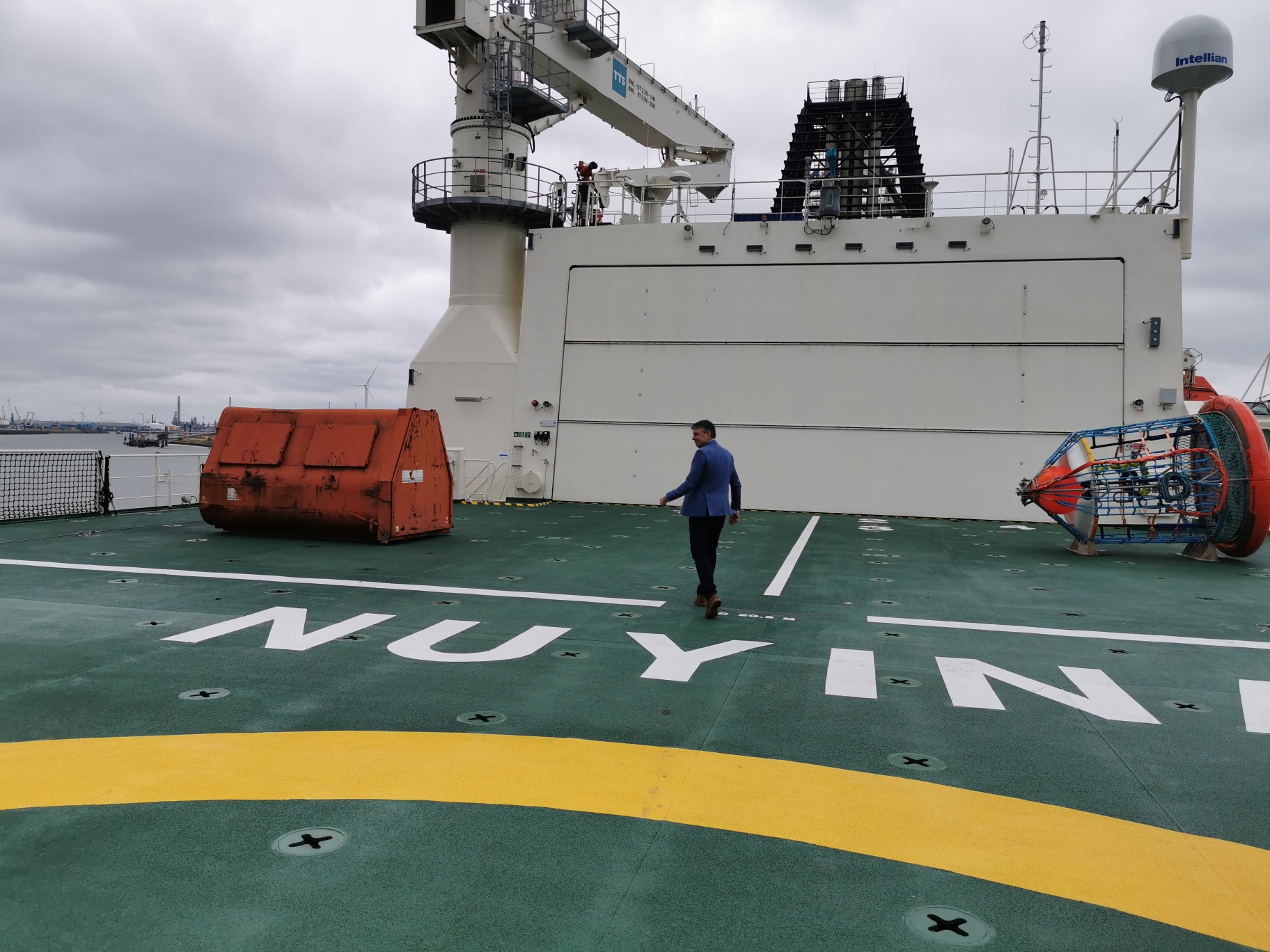
Damen project director Joop Noordijk on the helicopter deck.
The helicopter hangar.
The funnel house has been arranged in front of the hangar.
Further forward, a large deckhouse contains two more layers for accommodation and a hospital area. This includes an operating room, doctor’s surgery and sick bay for four patients. The lowest tier consists of two-person cabins for scientific personnel and crew. Officers and leading scientists are accommodated in single cabins in the tier above.
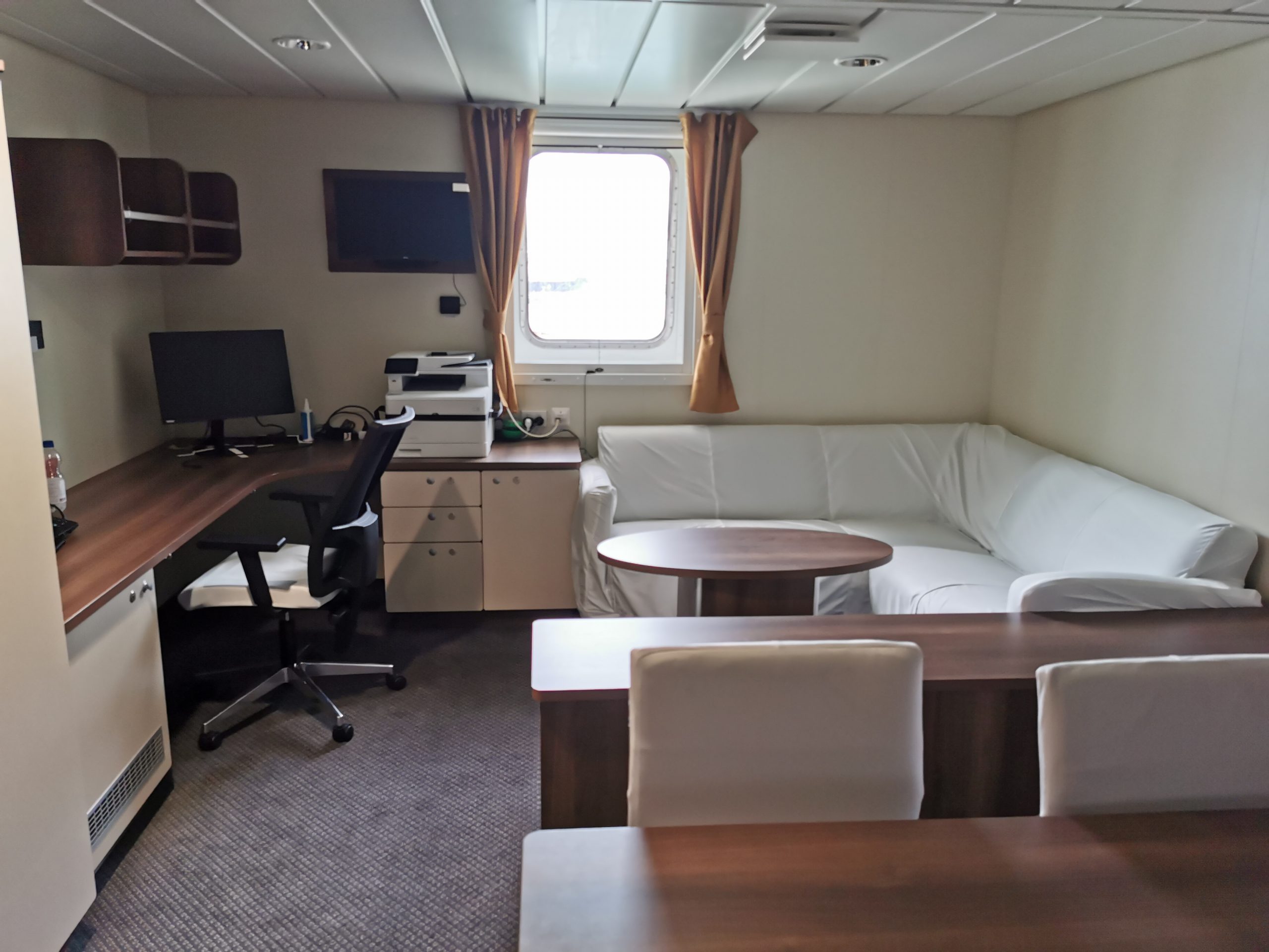
The officer cabin has a separate bedroom and shower.
An observation space and a wheelhouse are located on deck-9 and deck-10 respectively. Large windows are fitted all around these spaces. The observation room is dedicated to scientific personnel and keeps the bridge reserved for the crew. The bridge wings extend significantly outside the hull for better visibility during icebreaking
and the various operations near the ship’s sides.
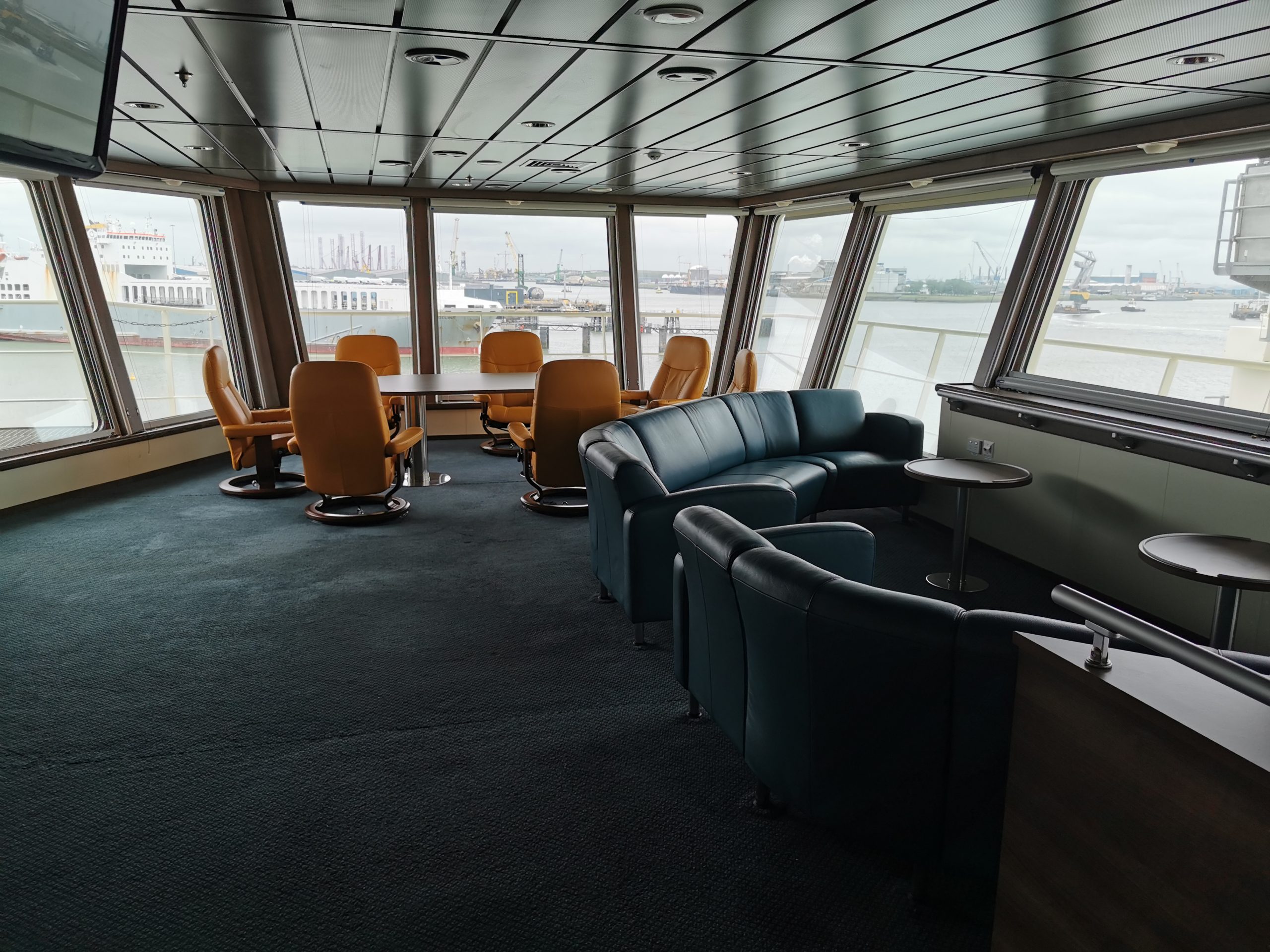
The observation lounge just below the bridge.
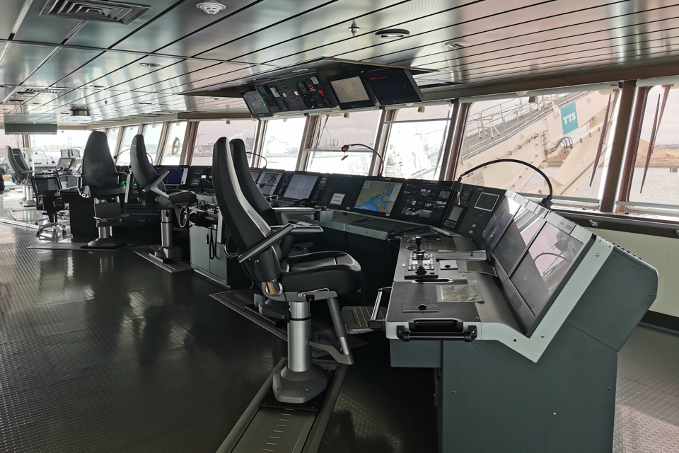
The bridge.
Hybrid power generation system
The propulsion system consists of two diesel-hybrid propulsion trains. Each train consists of a non-reversible marine diesel with gearbox, coupling and shaft. They drive controllable pitch propellers in diesel direct (DD) mode. The diesels are mounted in separate engine rooms, and are rated 9600 kW each at 750 rpm.
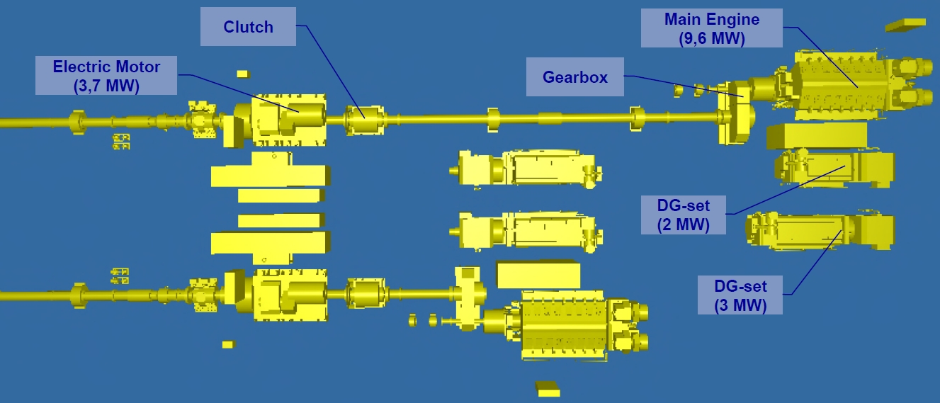
Each shaft is equipped with a motor/generator that can be connected via a shaft coupling. The generator function is called power take-off (PTO), the motor function power take-in (PTI). PTO is used in transit, supplying electrical power to the vessel’s electrical grid. During ice breaking and ramming, the installation is in diesel direct and PTI mode at maximum power.
A maximum shaft speed will then be combined with minimum propeller pitch. At ship design speed, the propellers will be running at maximum shaft speed and maximum pitch. The configuration enables many combinations of thrust and speed in between, controlled by the diesel, propeller and power management systems ensuring an energy efficient propulsion system.
In silent mode, the main diesels and gearboxes will be decoupled. The diesel electric propulsion system will then be operated. ‘The ship had to be able to operate in silent mode in speeds up to 8 knots,’ explained Noordijk. ‘However, we found out during trials in Norway, where we used underwater microphones to measure the ship’s noise, that the Nuyina can operate silently up to a speed of 13 knots. This also means that when the ship is sailing normally, it can operate in diesel electric mode.’
The Nuyina during the trials in the Norwegian fjords.
The vessel’s electric grid is powered by four, double resilient mounted diesel generators. They are arranged in pairs in the main engine rooms. Electrical power is supplied to the medium voltage switchboards, also in a dual arrangement. The main switchboards feed the shaft propulsion motors (PTI) when connected, or receive power from these units as shaft generators (PTO).
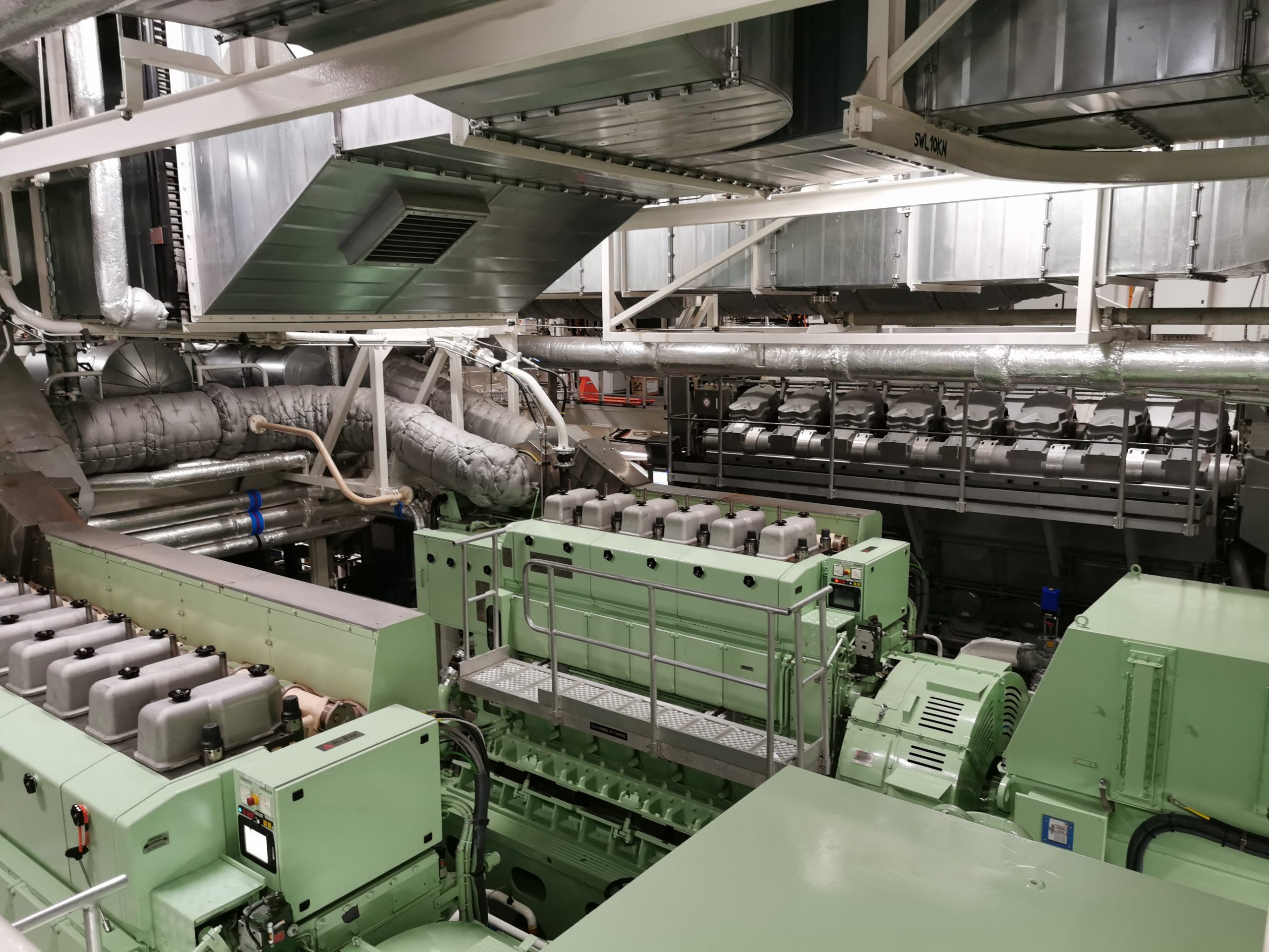
Engine room.
Three tunnel thrusters are fitted in the bow as well as the stern skegs to assist the vessel in station keeping up to sea state 6 and 8 BFT. In dynamic positioning mode, one switchboard will feed two bow thrusters and one stern thruster, the other one feeds two stern thrusters and one bow thruster. The main propellers remain in diesel direct mode with the power take-off online.
In DP failure mode, an intact switchboard will feed a missing bow or stern thruster connected to the failed switchboard. Upon a diesel failure, the related propeller shaft can be driven by its PTI device, receiving power from the electric grid. The two 690 V boards are connected to transformers, feeding two 400 V auxiliary switchboards and subsequently two 230 V switchboards for domestic services. These loads can be as high as 1400-1800 kW in polar conditions with all electric heating online. All switchboards are arranged in a dual setting.
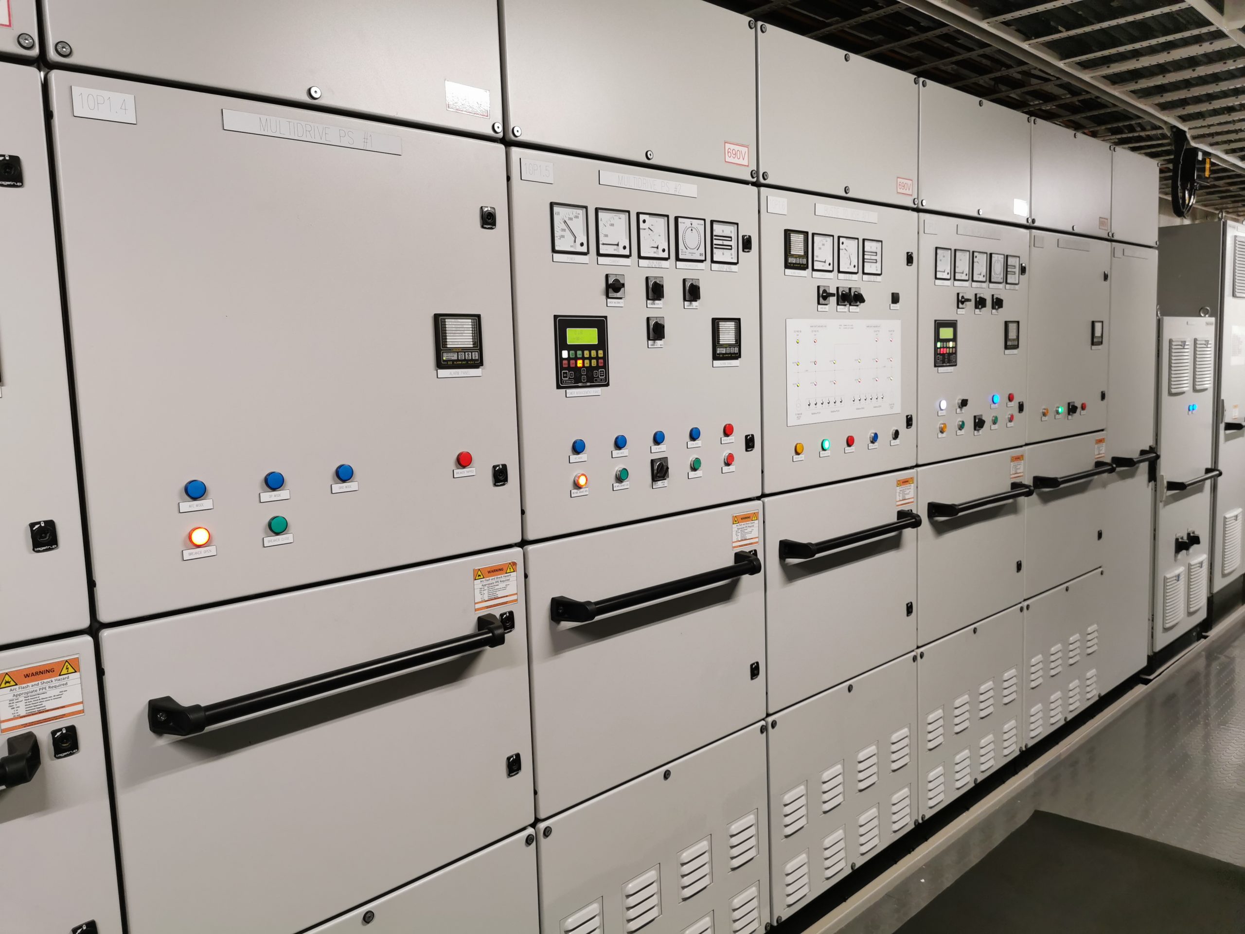
Switchboards.
Special outfitting and equipment
An A-frame is mounted on the aft work deck, along with a variety of winch systems for the deployment of ocean research equipment. This includes a trawl system, an ROV system and geotechnical equipment. In icefields, the smaller units must be deployed through the moonpool. Science equipment is normally lowered in ship stationary conditions, but the arrangement also allows for equipment being towed at low speed.
The moonpool has an internal wave attenuation system and is equipped with an oil skimmer. It can be closed at deck and bottom levels to prevent ice ingestion.
The two smaller wells for drop keels are also equipped with hatches. The drop keels are normally retracted, but can be lowered 3 m below keel. They are equipped with sensors for oceanographic research and can be lifted above the waterline for replacing equipment.
The work deck provides storage space for science containers. These are TEU sized units based on a modular philosophy. They can be connected to a variety of science systems, including power, alarm monitoring, aquarium water circulation over the ship’s tanks, and ventilation.
Since the ship must be self-supporting during its mission, all cargo and work spaces are well equipped with lifting gear or underdeck gantry cranes. The holds and stores are provided with material handling equipment for internal transfer of pallets. This includes a cargo lift and gantry cranes. Within the holds, free space is reserved for access to the containers. This enables onboard supply to science locations, but also unpacking and preparation of cargo for air and over water resupply. The holds are served by two knuckle boom cranes (55 t) and by a cargo door/loading platform.
Tender boats are mounted on the sides of deck-5, three at portside and one at starboard side. The tender boats will be deployed through recesses in the side walls and used for transferring shifts of scientists to the shore stations. One tender is specialised for scientific work and is provided with a suite of science sensors, its own towing frame and a small moonpool.
Two landing barges can be stowed on the aft hatch on weather deck and can be deployed by the main cranes. The barges are equipped for the transport of containers and vehicles. Forward of the hatches, the deck is protected by a long forecastle. It provides space for a retractable gangway (12 m) that can be deployed through a bow door. The gangway is designed for transfer of personnel and small loads on the ice floe.
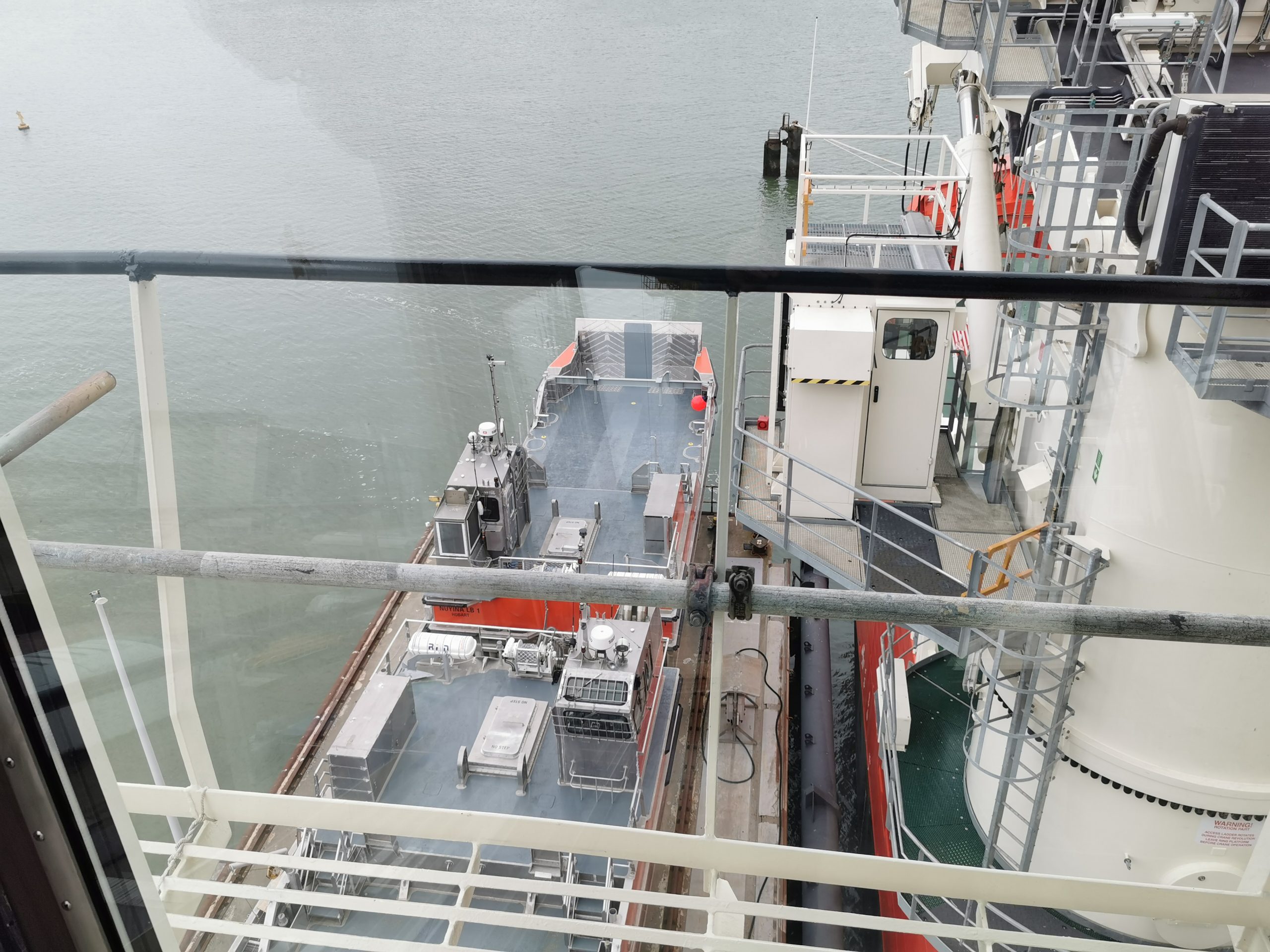
The landing barges (one of them seen here from the bridge) were built in Australia and transported to the Netherlands to be placed on board the Nuyina.
Liquid cargo (SAB) can be pumped ashore via floating hoses, assembled in special container units. In the near future, onboard provisions will be made to convert SAB tanks to Jet A1 aviation fuel. It is now stored in drums. Fresh water will be produced on board for delivery to the stations.
Survival in open sea and in the Antarctic
Totally enclosed life boats (126 and 75 passengers) have been arranged on both sides of deck-7. The larger ones provide more seats than required, but Damen has specified extra capacity for stowing survival equipment and emergency rations. This suits the survival scenarios in remote locations, as it can take a long time before being rescued.
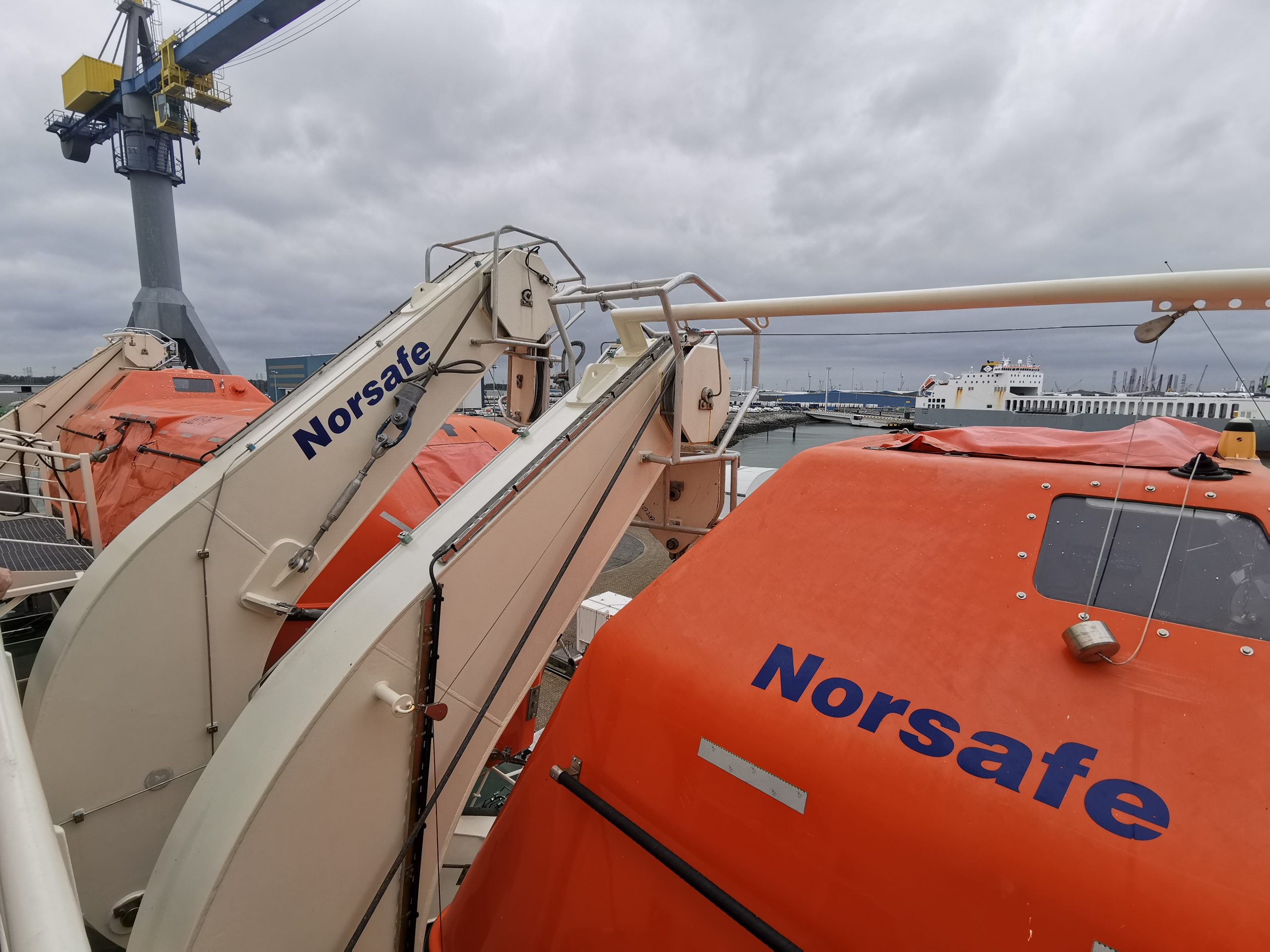
The Nuyina’s enclosed lifeboats.
According to Noordijk, survival kits on board the ship include essentials such as warm clothing, food, sun glasses and sun screen.
In the unlikely event of a ship casualty in ice, embarkation and survival on sea ice is required, awaiting rescue by other vessels. Survival equipment and emergency rations for ninety days will be kept on board for the entire complement. It involves two fully loaded TEU units which can be deployed with a crane onto the ice. The crane will then be powered by the emergency switchboard.
These extra provisions can also be used for a possible survival on board when the ship becomes beset by ice. A safe haven zone has been arranged comprising the mess room with lounge, the availability of sanitary facilities, the hospital and the wheel house for external communication. People will sit and sleep in shifts. Meanwhile the ship’s power consumption will be reduced to a bare minimum to ensure survival for months.
Also read: Video: Giant Australian icebreaker heads to Vlissingen for sea trials